Cambelt and Timing Information.

Gates Technical Information for Cambelt Timing on the Z20LEx 2.0 Turbo family of engines; Z20LET, Z20LEL, Z20LER and Z20LEH (Astra H VXR). This is not a ‘How To’ guide but gives additional technical information for those with enough mechanical competency to carry out a cam belt change.

Cambelt Change Cycle suggested by the manufacturer:
Z20LET :: 4 years* or 40,000 Miles*
Z20LEL :: 8 years* or 80,000 Miles*
Z20LER :: 8 years* or 80,000 Miles*
Z20LEH :: 8 years* or 80,000 Miles*
*Whichever occurs first.
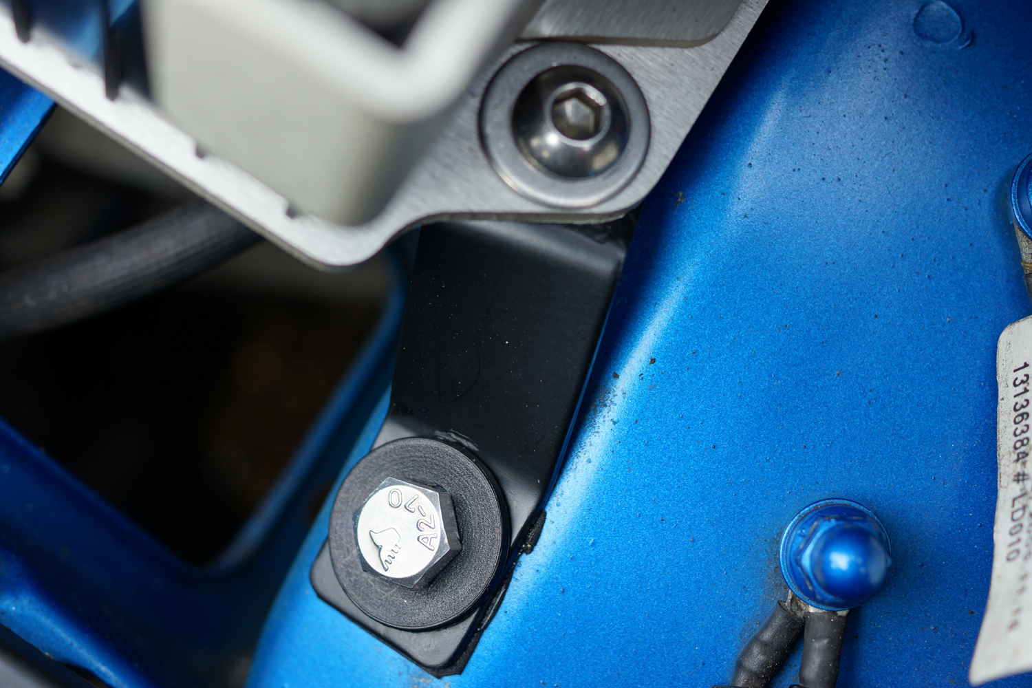
Notes: The cambelt (timing belt), plastic inlet roller and tensioner are common between all the engines (i.e. the same parts). The only different is that the LEL/LER and LEH kits use a metal exhaust roller (LET uses a plastic exhaust roller). For this reason I would suggest a 6 years* or 60,000 Miles* change cycle as best practice. Always use a new tensioner retaining bolt.

What is Needed……
As well as a good toolkit, with a good selection of sockets, allen head sockets, and male torx sockets, a 15mm spanner (or similar) to release tension on the auxiliary drive belt and a 17mm ½” drive socket and ratchet (makes turning the engine over to check tension much easier), you will also need for the later engine a very high quality T40 Male Torx ⅜” drive socket and a Camshaft Locking Tool such as a Draper CLT2 (Ref: 69929) or CLT-GM2 (Ref:61276) or similar. Also a ¼” drive E10 female torx socket (a slim one) is useful for removing the timing belt cover bolt next to the tensioner once the tensioner is in the ‘rest’ position.

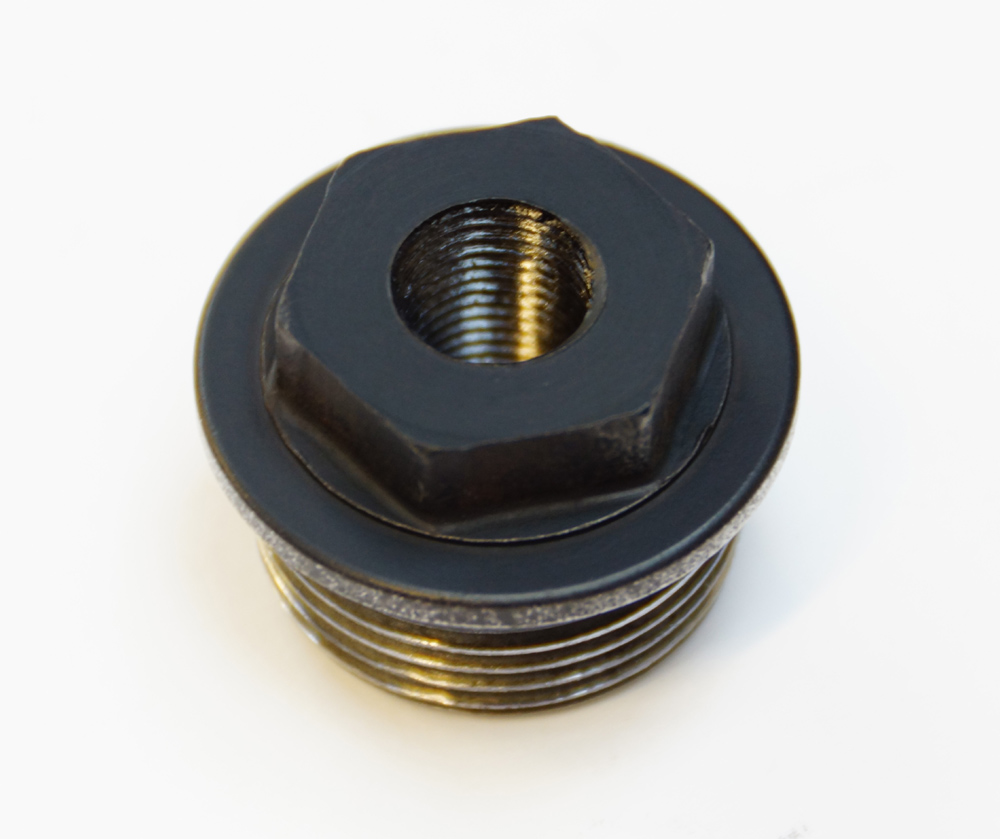
The T40 Torx is required on the later engines for tightening the cambelt tensioner retaining bolt. It has a very shallow head and if you are not careful the socket can slip and/or chew out the head of the bolt. I only use a Snap On torx for this particular tensioner retaining bolt because they are particularly strong, and it gets used for nothing else other than this particular bolt so it doesn’t get general wear and tear or other damage.

Example Camshaft Locking Tools:

Camshaft Locking Tool

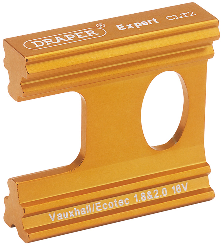
Camshaft Locking Tool CLT2

Camshaft Locking Tool

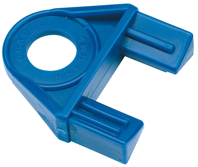
Camshaft Locking Tool CLT-GM2

When changing the cam belt always check the water pump and replace if in any doubt, especially on later engines where the change cycle of the cam belt is longer.

Gates Technical Data Sheet on how to time up the engine: PDF – Timing Information (4.8Mb)
Note: You will need a PDF reader for this file

PDF Icon

PDF – Timing Information

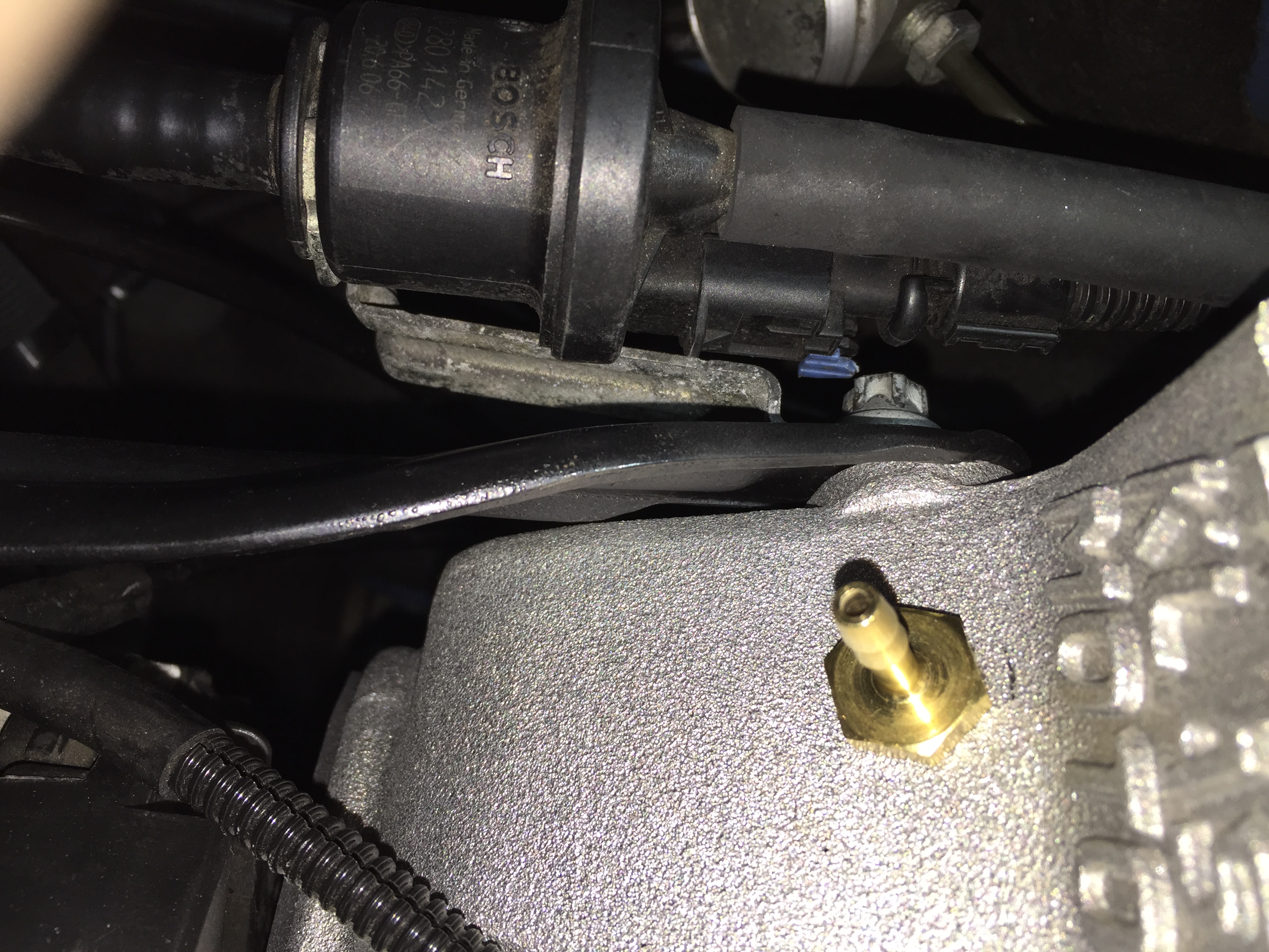
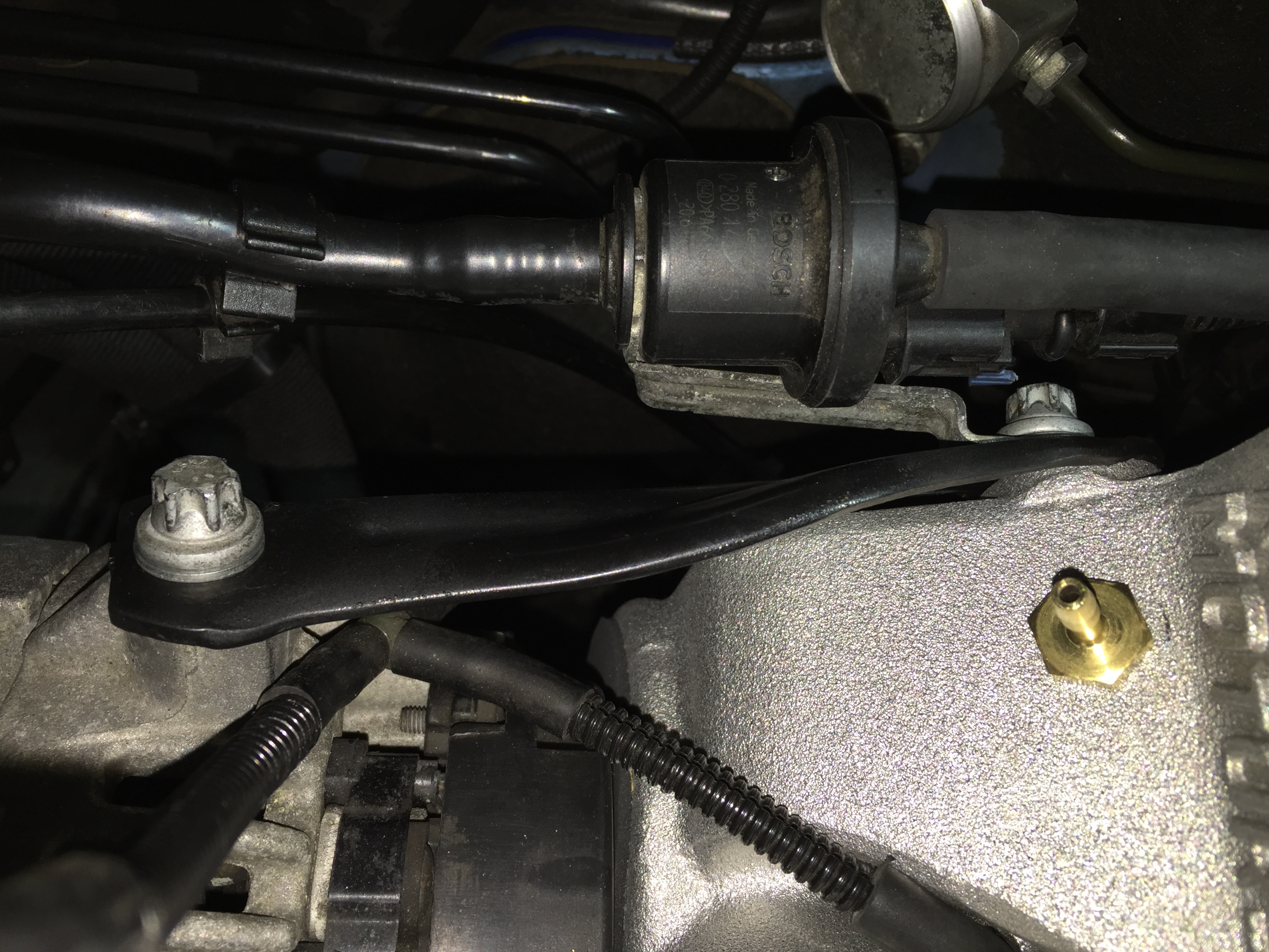
Remember the tensioner is tensioned ANTI-Clockwise!!

Timing Pointer - Correctly Tensioned

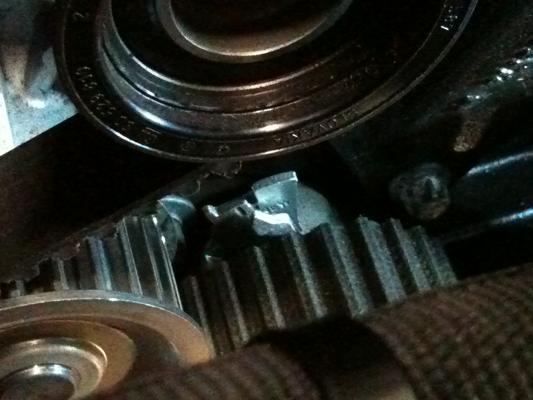
Timing Pointer – Correctly Tensioned

Note: E&OE. The above Technical Guidelines are provided for information only. No responsibility is accepted for damage, loss, injury or general stupidness. If you are not sure on exactly what you are doing when it comes to cambelt replacement, leave the job to a professional who does…. That is all.

Evans Power Cool 180 Waterless Coolant

I was introduced to Evans Waterless Engine Coolants a while ago when one of their distributors dropped a flyer into a package that I was sent and also at the AutoSport International Show at the NEC in Birmingham. Having read up about the benefits of using it, it seemed the ideal time to switch to it after the engine had been stripped down to have the steel rods fitted, as the majority of the original coolant had already been drained.

So a phone call directly to Evans and this package arrived 24 hours later:

Evans PowerCool 180 Waterless Engine Coolant

Evans PowerCool 180 Waterless Engine Coolant

The Evans website details everything you need to know about the products but in brief:
Eliminates Overheating – Evans Waterless Coolants have a boiling point above 180°C and will not vapourise, thus eliminating overheating, boil-over and after-boil.
Reduces Pressure – Evans Waterless Coolants generate very low vapour pressures reducing strain on engine cooling system components.
Prevents Corrosion – Evans Waterless Coolants contain no oxygen effectively eliminating corrosion.
Increases BHP – Evans Waterless Coolants eliminate pre-ignition and detonation caused by overheating – thus improving combustion efficiency and delivering more power.
Stops Erosion – Evans Waterless Coolants prevent cavitation and eliminate liner and cooling pump erosion.
Freeze Protection – Evans Waterless Coolants freeze below -40ºC
Non-Toxic – Evans Waterless Coolants are proven to be Non-Toxic. Standard anti-freeze is toxic and known to kill pets.

One of the main things that drew me to the product was the reduction in pressure in the coolant system. One of the slightly annoying things with traditional water based coolant is the fact that it is operating in a pressurised environment and when hot it expands. In the Astra H VXR when on track and used hard, if the coolant level starts at the recommended cold level, it pressurises coolant out of the bleed point at the back of the header tank cap all over the engine bulkhead.

Even if the level is dropped to about 1cm below the cold level (when cold) when hot the level will rise and it can still pressurise out of the header tank. This product will eliminate the problem due to the removal of all the water and the reduction in the pressure in the system. Also the reduction in pressure will put less strain on all the coolant system components and hoses; another benefit when on track.

I chose the Power Cool 180 for performance and track cars, and set about filling with the Evans Prep Fluid to hygroscopically remove any traces of the original coolant, drained the system when cold and blew it through from the header tank hose and from the thermostat to remove all the Prep Fluid. The system was then filled with a shade over 7 litres of Evan Power Cool 180.

I will update on progress when out on track but so far with rolling road set up runs, no problems at all. In my opinion every car used out on track should have this product installed.

Just Remember……..

Water for Drinking Evans for Cooling

Water for Drinking Evans for Cooling

Almost There

Almost back together. Just the gearbox oil cooler pipework to finish off (from the gearbox to the oil pump), the slam panel can now go back in and add the Evans PowerCool 180 Waterless Coolant.

Engine Bay Nearing Completion

Engine Bay Nearing Completion

Odyssey Motorsport Battery

The Odyssey lightweight motorsport battery came about for a couple of reasons. Firstly the battery on the road car died, and needing a battery for it in a hurry I ‘borrowed’ the Yuasa battery that was originally fitted to the track car.

So the option was to either replace it with another heavy wet cell car battery for about 50 quid or to justify the additional expense of a smaller much lighter weight motorsport battery. Simple choice really!

The Odyssey PC680 has enough capacity to run a 2.0 engine is much smaller than a ‘normal’ battery and weighs only 6.65kgs (despite the battery label stating 7kgs!), compared to a typical car battery at 16kgs or so. The weight saving is ideal, especially because of the additional oil cooler and pump that have gone in.

So, one Odyssey Extreme Motorsport Battery was ordered. The PC680 battery is only about 10mm taller than an original car battery meaning there is plenty of clearance on the bonnet and to make fitting simpler I specced it with SAE brass terminals to take the factory clamps, meaning no requirement to alter any of the cabling:

Odyssey PC680 Motorsport Battery

Odyssey PC680 Motorsport Battery

The next problem to be solved was how to mount the battery into the engine bay. There are plenty of functional battery clamps around for motorsport use for when a battery is mounted inside a vehicle, but very few visually appealing ones. Not wishing to have to make something from scratch, a search online discovered a hold-down clamp designed and sold by Odyssey.

Odyssey Battery Clamp

Odyssey Battery Clamp

Unfortunately despite searching I could not find it available in the UK but not wanting to be defeated kept searching and found it available online in the USA so went about importing it. Possibly at US$110 it could be considered expensive, but I felt that for something well manufactured and ideal for the job worth every penny!

So I set about trial fitting the clamp and the battery into the car. The great thing with this clamp is that it sits on the factory battery support (which is integrated into the chassis leg) and the bottom left hole in the battery clamp lines up perfectly with one of the original M8 battery bolt fixings.

Odyssey Battery Trial Fit

Odyssey Battery Trial Fit

To support the battery and clamp securely, Pro Alloy Motorsport made up a couple of additional supporting brackets to my supplied patterns. The first one, secures the bottom right fixing point to the OE pickup point on the chassis leg:

Mounting Bracket

Mounting Bracket

The second bracket is a U shaped one and bolts to the clamp in 2 points and across onto the remaining pick up point on the chassis leg:

Mounting Bracket

Mounting Bracket

All mounted securely, just the battery leads to be connected:

All Fitted - Just needs connecting up

All Fitted – Just needs connecting up

And there is plenty of clearance between the battery clamp securing bracket nut and bolt closest to the chassis leg (which is at the top of the picture) and the clutch feed pipe which runs underneath just in front of the gearbox mount.

Clearance on Clutch Pipe

Clearance on Clutch Pipe

Dual Oil Temperature Gauge, Boost Gauge and Dual Gauge Vent Pod

To monitor both engine oil and gearbox oil temperatures a suitable gauge is required. Rather than two cheaper gauges, meaning extra work on installing them and finding a suitable location in the car, I tracked down this SPA Digital Dual Oil Temperature Gauge. Relatively expensive at around £190 but worth the cost due to the features it offers and:

Spa Dual Digital Oil Temperature Gauge

Spa Dual Digital Oil Temperature Gauge

It comes with twin wiring looms and two oil temperature sender units which means the only wiring that is needed is a switch feed (with a 250 mA fuse) and an earth, so pretty simple on that front:

Spa Dual Digital Oil Temperature Gauge

Spa Dual Digital Oil Temperature Gauge

Fitting for the Engine Oil Temperature Sender, which is located into the back of the oil pump. This blank plug is fitted into the factory oil pump. It has been drilled and tapped to accept one of the supplied temperature senders. It will be refitted with a new sealing washer:

Engine Oil Temperature Fitting

Engine Oil Temperature Fitting

Fitting for the Gearbox Oil Temperature Sender, which is a Speedflow fitting (M18x1.5 to ⅛th NPT) sourced from Australia. This is located into the front of the gearbox where the level check plug would otherwise be, and will be fitted with a new sealing washer supplied with the fitting:

M18x1.5 to ⅛th NPT Adapter

M18x1.5 to ⅛th NPT Adapter

Sender Units installed into fittings (engine oil – left, gearbox oil – right):

Senders Installed into Fittings

Senders Installed into Fittings

Gearbox Oil Temperature Sender:

Gearbox Oil Temperature Sender

Gearbox Oil Temperature Sender

Engine Oil Temperature Sender:

Engine Oil Temperature Sender

Engine Oil Temperature Sender

Next was the issue of where to mount the gauge. So a dual gauge facia (front for a vent pod) was bought from ebay for the SPA Gauge and the Boost Gauge which is designed to sit in the right hand air vent.

I then set about modifying the right hand air vent housing to accept the facia. Several hours of cutting and shaping with a multi tool later and the facia was bonded to the housing. The supplied facia is gloss black:

Dual Gauge Pod

Dual Gauge Pod

And from the rear with two OE plastic captive nuts to allow the complete assembly to be held into the car securely:

Dual Gauge Pod - Rear

Dual Gauge Pod – Rear

Not happy with the gloss black finish the facia was prepped and sprayed in Matt Black:

Dual Gauge Pod - Satin Black

Dual Gauge Pod – Satin Black

And with both gauges fitted ready to go into the car. The comprehensive wiring supplied with the SPA gauge means that the only connection into the gauge is a 12 pin multi plug, that simply plugs in, and the boost gauge has a vacuum/boost line run to it from the engine (fuel pressure regulator vacuum pipework) and an illumination feed for when the headlights are on to illumine the gauge. This feed was run into the car from the feed to the side light from the right hand headlight loom as a 12v feed is needed (the bulb in the gauge is 12v):

Gauges Installed

Gauges Installed

Gauges Installed

Gauges Installed

Picture from under the dash showing the retaining screws (just visible centre and top left) secured through the original air vent plastic pipework and into the captive nuts in the gauge pod, which all one up when the gauge pod is pushed fully home:

Retaining Screws

Retaining Screws

Gauges installed and functioning. Boost Gauge (Left) and Dual Oil Temperature Gauge showing the Engine Oil Temperture (Top) and Gearbox Oil Temperature (Bottom. The functions and settings for the SPA gauge are controlled by the red push button mounted on the steering cowl, visible bottom left of picture:

Gauges Installed

Gauges Installed


Aeromotive Uprated Fuel Pump

With the increase in power over the winter period, another area that can be looked at is the fuel pump.

Whilst the factory fuel pump is capable of providing enough fuel for up to round 340bhp or so as they get older there is a possibility that their capability will drop off. For road use the factory pump is more than capable, and it will in most cases be fine for track use, however since there is a good uprated alternative available it makes sense to opt for it.

The Aeromotive in tank fuel pump is capable of providing fuel for for engines producing 450bhp or so, which means it is the ideal choice for track work at the sort of power the car is producing.

Aeromotive Stealth In Tank Fuel Pump. It is slightly ‘fatter’ than the factory fuel pump:

Aeromotive Stealth In Tank Fuel Pump

Aeromotive Stealth In Tank Fuel Pump

In Tank Fuel Pump Housing In-Situ, with wiring loom plug and fuel pipes connected (Return – Left :: Feed – Right). Access under the plastic bung under the seat base:

Fuel Pump Housing

Fuel Pump Housing

Fuel Pump Housing Locking Ring Removal Tool. Requires a little care and a ½” breaker bar. Disconnect the wiring loom plug and both fuel lines first, taking car to soak up any split fuel with rag (note: make sure the battery has also been disconnected):

Securing Ring Removal Tool

Securing Ring Removal Tool

Which once unclipped from the in-tank cage allows the

OE Fuel Pump Housing

OE Fuel Pump Housing

The clips that hold the fuel pump housing into the in-tank cage are arrowed. These must be unclipped to allow the complete housing to be lifted clear of the fuel tank. The hardest one to reach is the one under the fuel sender float (bottom right of the picture). When removing the housing carefully tip any fuel in the housing back into the tank, and use rag to soak up any excess as the housing is lifted clear:

Fuel Pump Housing Securing Clips

Fuel Pump Housing Securing Clips

In-Tank cage which corresponds with the clips on the fuel pump housing. Again the hardest one to access when the housing is in the tank is the one shown at the top of the picture:

Fuel Pump Housing Retaining Cage

Fuel Pump Housing Retaining Cage

To remove the factory fuel pump, first gently heat the plastic fuel pipe to allow it to be removed. Take care not to melt or break it, however replacement convoluted fuel pipe is available. Unclip the 2 pin wiring connector (which will fit the new pump) and then unclip the plastic cover that holds the OE fuel pump into the tank (there are a couple of clips each side) and the pump can be lifted clear. Now is a good opportunity to give the housing a good wash out.

The aeromotive pump can be dropped into the in-tank housing, and the upper plastic cover which holds the pump in the housing needs to be gently opened out to slide over the new pump, which is slightly fatter. Where the plastic upper cap, which retains the pump into its housing, has to be modified they can become brittle with age and the inner retaining lip comes away. The OE fuel pump is slightly narrower at the top, hence why the retaining cap has to be modified to allow the new pump to fit into it. To ensure a secure fit and to prevent the fuel pump from lifting, some additional sleeving (supplied with the fuel pump) has been used with a cable tie and some securing screws. The pump now sits very securely in the housing with no movement.

Pump Fitted to Housing

Pump Fitted to Housing

The original fuel pipe is then gently warmed and slipped back over the fuel pump outlet and an additional hose clip added for additional security:

Pump Fitted to Housing

Pump Fitted to Housing

Carefully return the complete housing back into the tank and make sure it is clipped back in place. Then refit the upper cover and seal. The seal underneath is a bit awkward to get to seat in the recess of the tank as it needs to be stretched slightly to fit but then doesn’t stay in the recess. Several small blobs of RTV neatly applied in about 6-8 locations around the recess hold the seal in place long enough to get the cover fitted. If the seal isn’t seated correctly, the cover will not sit flush to the seal and the tank will leak.

Then refit the metal retaining ring and reconnect the wiring plug and both fuel lines. The plastic access bung can then be refitted.

Fuel Pump Housing

Fuel Pump Housing

High Flow Courtenay Klasen Inlet Manifold

So the addition of this high flow inlet manifold will help to give more mid range and top end power, complimenting the K06 turbo and the steel rods.

High Flow and OE Manifold Inlet Manifolds

High Flow and OE Manifold Inlet Manifolds

OE Manifold and High Flow Inlet Manifolds

OE Manifold and High Flow Inlet Manifolds

OE Manifold and High Flow Inlet Manifolds

OE Manifold and High Flow Inlet Manifolds

4mm Thick Thermal Inlet Manifold Gasket to help reduce heatsoak from the head into the new inlet manifold:

4mm Thick Thermal Inlet Manifold Gasket

4mm Thick Thermal Inlet Manifold Gasket

Longer studs are fitted when used with a thermal inlet manifold gasket:

Replacement Studs

Replacement Studs

Inlet Manifold Fitted:

Inlet Manifold Fitted

Inlet Manifold Fitted

Inlet Manifold Fitted

Inlet Manifold Fitted

Both Alternator brackets require the holes opening up slightly so as not to pull the alternator out of alignment when used with the new inlet manifold:

Alternator Mounting Brackets

Alternator Mounting Brackets

The brackets refitted:

Alternator Bracket Fitted

Alternator Bracket Fitted

Steady Bracket Fitted

Steady Bracket Fitted

Alternator to Inlet Manifold Bracket

Alternator to Inlet Manifold Bracket

To aid fitment of this bracket (shown fitted above) a slight bend to the right hand end will align the bracket to sit flush with the inlet manifold, and carefully removing a short section of the lower return lip of the bracket will give additional clearance against the manifold.

Alternator to Inlet Manifold Bracket

Alternator to Inlet Manifold Bracket

And the factory servo vacuum pipe needs to be heated and shaped slightly to fit onto the new inlet manifold:

Servo Pipe Modified to fit new Manifold

Servo Pipe Modified to fit new Manifold

Servo Pipe Modified to fit new Manifold

Servo Pipe Modified to fit new Manifold

And this is the OE location of the servo vacuum pipe:

OE Manifold Servo Pipe Location

OE Manifold Servo Pipe Location

Thermostat Housing Water Return Pipe

The thermostat housing water return pipe (which runs across the face of the head) was starting to show its age with some slight surface corrosion and the odd spot of rust on the mounting brackets so I decided to prep it and paint it Matt Black, with the same Wurth Heat Proof paint as before, to compliment the Matt Black Exhaust/Turbo Heat Shield (see Exhaust Heatshield in Build 2012):

Water Return Pipe in Matt Black

Water Return Pipe in Matt Black

The ends of the water pipe were masked off and not painted as this is where the rubber water pipes are pushed on and secured with hose clips.

This is what a factory engine bay looks like with the original heat shield and water return pipe:

Original Heat Shield and Water Return Pipe

Original Heat Shield and Water Return Pipe

And this is what the two painted parts look like fitted. Finishes off the engine bay much better:

Water Return Pipe and Exhaust Heat Shield in Matt Black

Water Return Pipe and Exhaust Heat Shield in Matt Black

Gearbox Breather Tank – Updated

Due to the changes to the car for 2014, the addition of a gearbox oil cooler means that one of the breather pipes into the gearbox breather tank needs to be removed, because it is now being used as the oil return to the gearbox from the oil cooler matrix.

So a slight change to the breather pipes was made converting one breather outlet from the gearbox to a twin outlet for the pipework back up to the breather tank. The single outlet from the gearbox is the factory breather point.

Gearbox Breather Modified Outlet

Gearbox Breather Modified Outlet

It all fits pretty neatly and clears the gearshift assembly on top tot the gearbox (just to the right of where the breather hose is hose clipped to the gearbox breather tube):

Gearbox Breather Modified Outlet

Gearbox Breather Modified Outlet

Engine Oil Cooler

Over the winter I have decided to do something about the gearbox oil temperatures, which when on track can get seriously hot, one of the downsides of the M32 is its inability to dissipate heat effectively. So installing a gearbox oil cooler was the logical upgrade.

So why am I installing an engine oil cooler if the engine already has one? The simple answer is because the engine oil cooler is a small water cooled laminova core, mounted to the rear of the block just under the inlet manifold and cooled by the engine coolant. Whilst this is good enough at keep oil temperatures in check for fast road and track use at 280 or so bhp, potentially it will start to struggle more as more and more power is added, so worth looking at upgrading as well.

By installing a gearbox oil cooler I will need to add an additional external cooler. The thought process is to use the original laminova core (originally the engine oil cooler) to act as a gearbox oil cooler because the gearbox only has 3 litres of oil, so if I am adding an extra oil cooler I though I would make it for the engine and use a bigger external oil cooler because I am getting to the limits of the factory oil cooler’s capabilities. By doing this I am still only adding one external cooler (for the engine) and re-using the exiting engine oil cooler for the gearbox oil  rather than having to add two (one for the engine AND one for the gearbox.)

So after a conversation with Think Automotive here is the chosen Mocal Oil Cooler, more than adequate for a 2.0 Turbo engine:

Mocal Engine Oil Cooler

Mocal Engine Oil Cooler

And a selection of black anodised aluminium oil cooler fittings:

Oil Cooler Fittings

Oil Cooler Fittings

also supplied by Think Automotive, who really know their stuff when it comes to this sort of thing.

I chose aluminium anodised over steel because I didn’t want any surface degradation and they look much better finished in black, albeit they are a more expensive fitting.

I also needed a selection of banjos and banjo bolts:

Banjos and Banjo Bolts

Banjos and Banjo Bolts

These are again aluminium anodised and somewhat expensive, however well worth the money (I couldn’t get them in black as they were out of stock and when I ordered them the lead time was too long). Supply came from Earl’s Performance in the UK, again very helpful. I chose these banjo fittings so that everything will screw together neatly. I did not want banjos with tails that have to be secured on with hose clips (however this type of banjo fitting is much cheaper in comparison!).

Finding somewhere to mount an additional oil cooler is great fun on an Astra where space is somewhat limited, but with the aircon condenser gone (it used to sit between the intercooler and water radiator) there is some available space. I mocked up the mounting brackets and then sent the Interooler to the guys at Pro Alloy Motorsport and asked them to fabricate some mounting brackets for the oil cooler, which would use Mocal rubber bobbins, and to also weld on a couple of additional bosses on top of the intercooler to securely locate the oil cooler.

And Pro Alloy produced four alloy mounting brackets:

Mounting Brackets and Bobbins

Mounting Brackets and Bobbins

And a pair of bosses welded onto the top of the intercooler:

Bosses added to Intercooler

Bosses added to Intercooler

Top work as always from the guys at Pro Alloy Motorsport 🙂

Next was to start to make up the oil hoses and fittings. I am using Aeroquip push on or socketless hose, which has a temperature operating range of -40 to +150 degrees C. Fitting is very simple and pretty straightforward. Construction is AQP elastomer inner tube & outer covering with textile braid reinforcement finished in black.

Oil Hose Fitting

Oil Hose Fitting

For the oil hoses I managed to track down some OE heat shrinkable fabric sleeve which is designed to protect from abrasion. Black Heatshrinkable Fabric Sleeving for additional oil cooler lines, to retain an OE look. Highly flexible heatshrink woven fabric tubing, Polyolefin/Polyester construction for excellent abrasion resistance 125°C operating temperature (excellent abrasion resistance to 135°C), Heat shrinkable to grip substrates tightly without additional fixing, Easy to install, Designed primarily to provide mechanical abrasion protection for components such as rubber hoses, plastic pipes and harness wiring bundles.

Heatshrinkable Fabric Sleeve

Heatshrinkable Fabric Sleeve

The easiest route for the engine oil cooler pipework is from the original take off plate above the oil filter and along the inner wing and past the headlight. This meant that the edge of the headlight housing had to be trimmed to give some additional clearance:

Headlight Assembly Modified for Clearance

Headlight Assembly Modified for Clearance

Headlight Assembly Modified for Clearance

Headlight Assembly Modified for Clearance

And then a suitable cover piece was cut from polycarb and painted black, then bonded onto the headlamp housing using RTV to give a water tight seal.

Cover Piece

Cover Piece

The oil cooler pipework routed alongside the headlamp unit to the new oil cooler:

Oil Cooler Hose Routed Past Headlight

Oil Cooler Hose Routed Past Headlight

Oil Cooler take off plate which is thermostatically controlled to regulate oil flow to the cooler, with banjos and banjo bolts fitted with new oil seals:

Oil Cooler Take Off Banjos

Oil Cooler Take Off Banjos

And here is the oil cooler fitted to the top of the intercooler, just waiting for its pipework. The top 7 rows of the new oil cooler will get direct air through the upper grille:

Oil Cooler Mounted to Intercooler

Oil Cooler Mounted to Intercooler

Provision has also been made for an oil temperature gauge sender, which has been installed into the spare fitting at the back of the oil pump. I had the plug drilled and tapped to take a ⅛th NPT oil temperature fitting:

Engine Oil Temperature Fitting

Engine Oil Temperature Fitting

More about this in the Oil Temperature Gauge post.

Astra VXR Sprint.....

%d bloggers like this: