Dual Oil Temperature Gauge, Boost Gauge and Dual Gauge Vent Pod
- Mar 29th. 2014
- By mapw
To monitor both engine oil and gearbox oil temperatures a suitable gauge is required. Rather than two cheaper gauges, meaning extra work on installing them and finding a suitable location in the car, I tracked down this SPA Digital Dual Oil Temperature Gauge. Relatively expensive at around £190 but worth the cost due to the features it offers and:
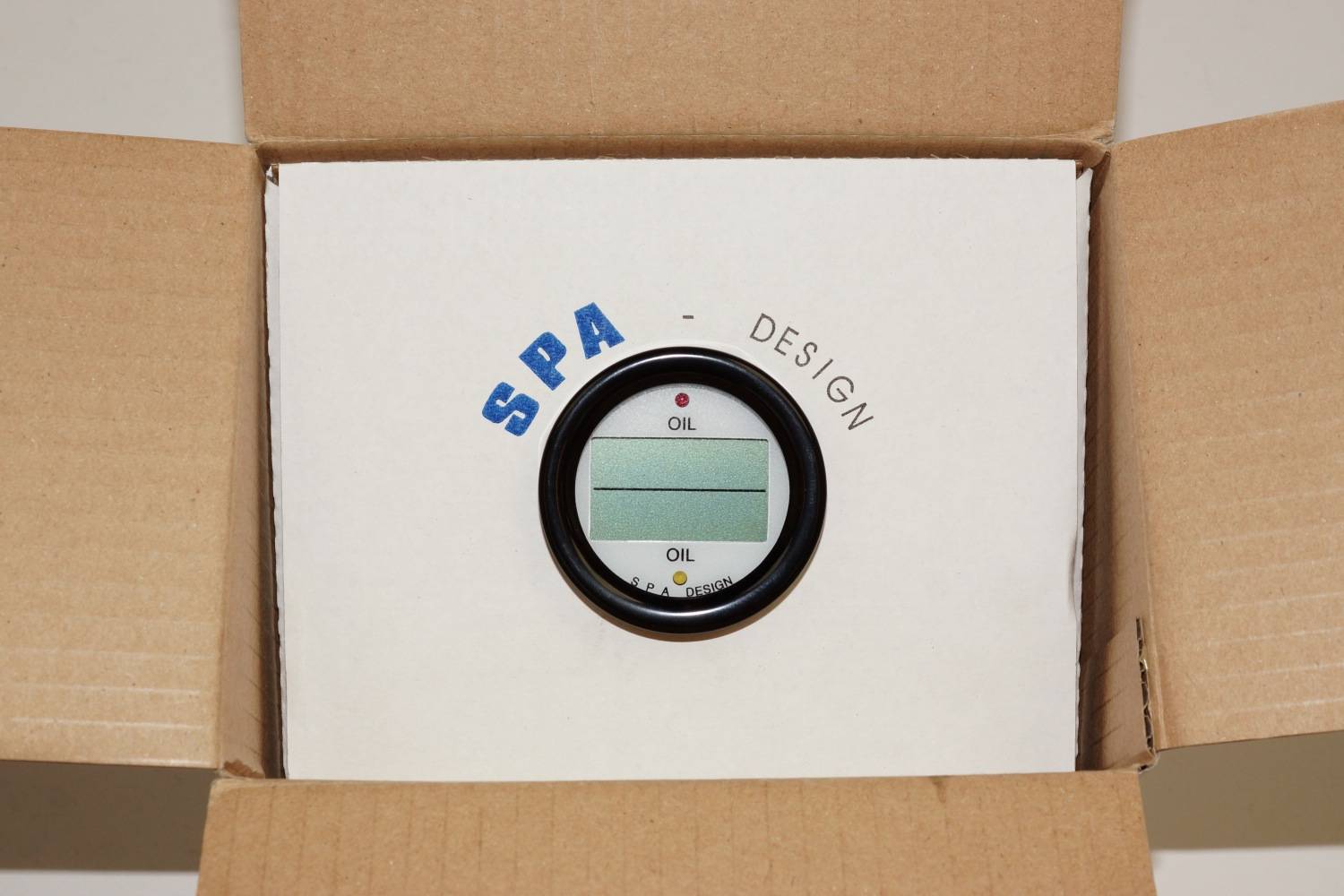
Spa Dual Digital Oil Temperature Gauge
It comes with twin wiring looms and two oil temperature sender units which means the only wiring that is needed is a switch feed (with a 250 mA fuse) and an earth, so pretty simple on that front:
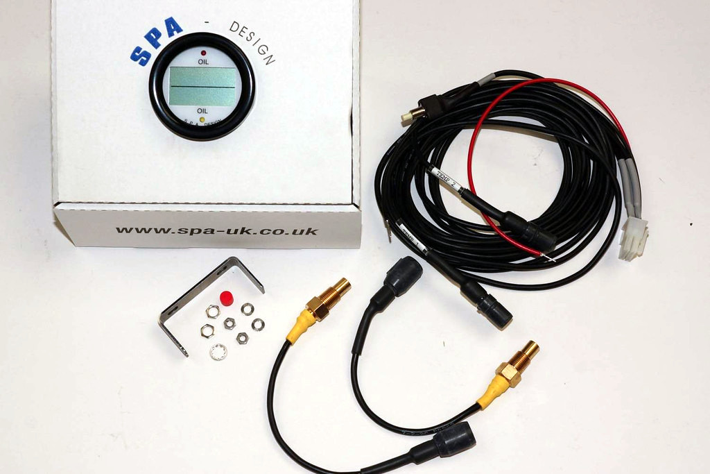
Spa Dual Digital Oil Temperature Gauge
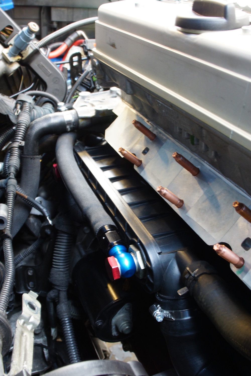
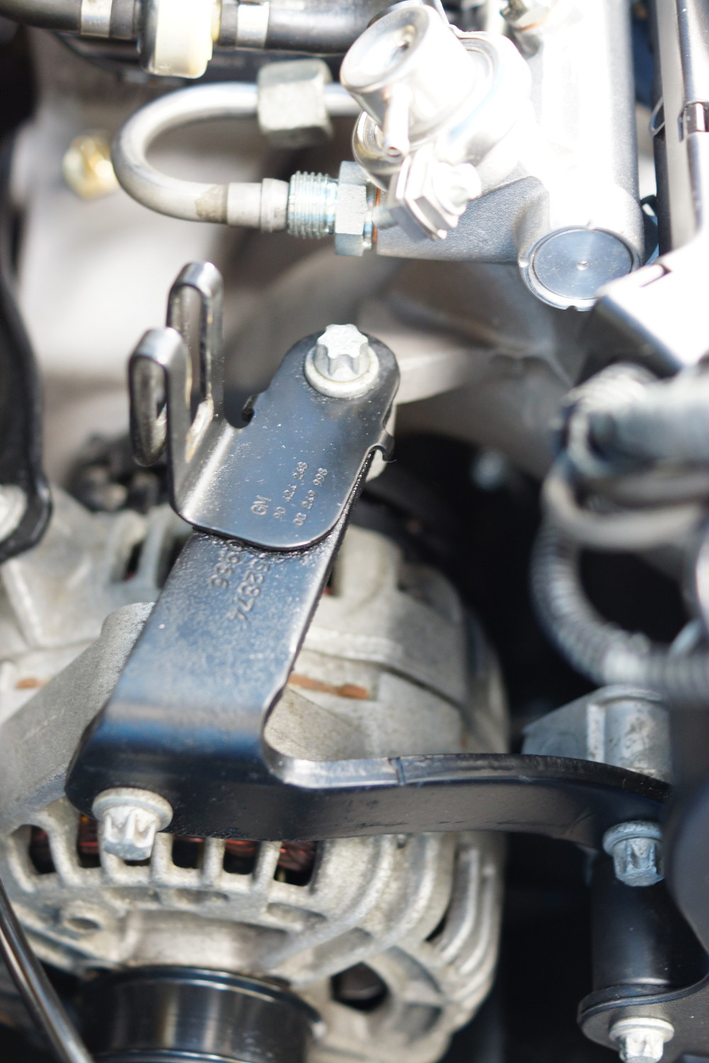
Fitting for the Engine Oil Temperature Sender, which is located into the back of the oil pump. This blank plug is fitted into the factory oil pump. It has been drilled and tapped to accept one of the supplied temperature senders. It will be refitted with a new sealing washer:
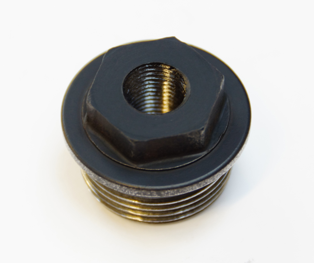
Engine Oil Temperature Fitting
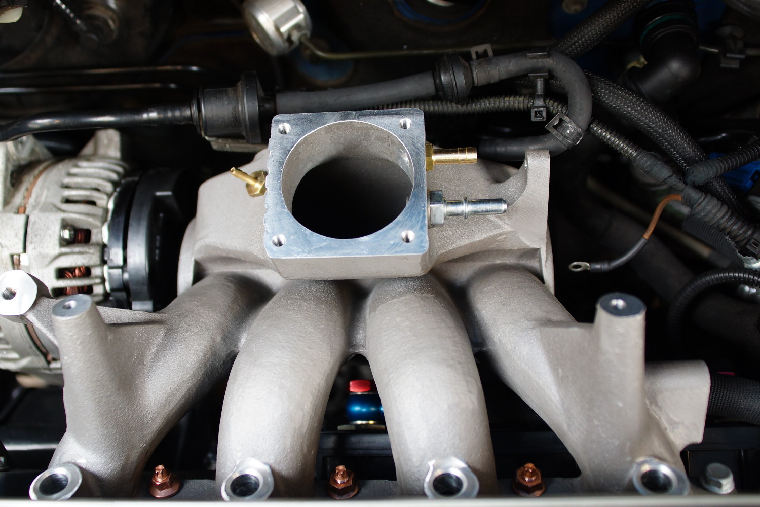
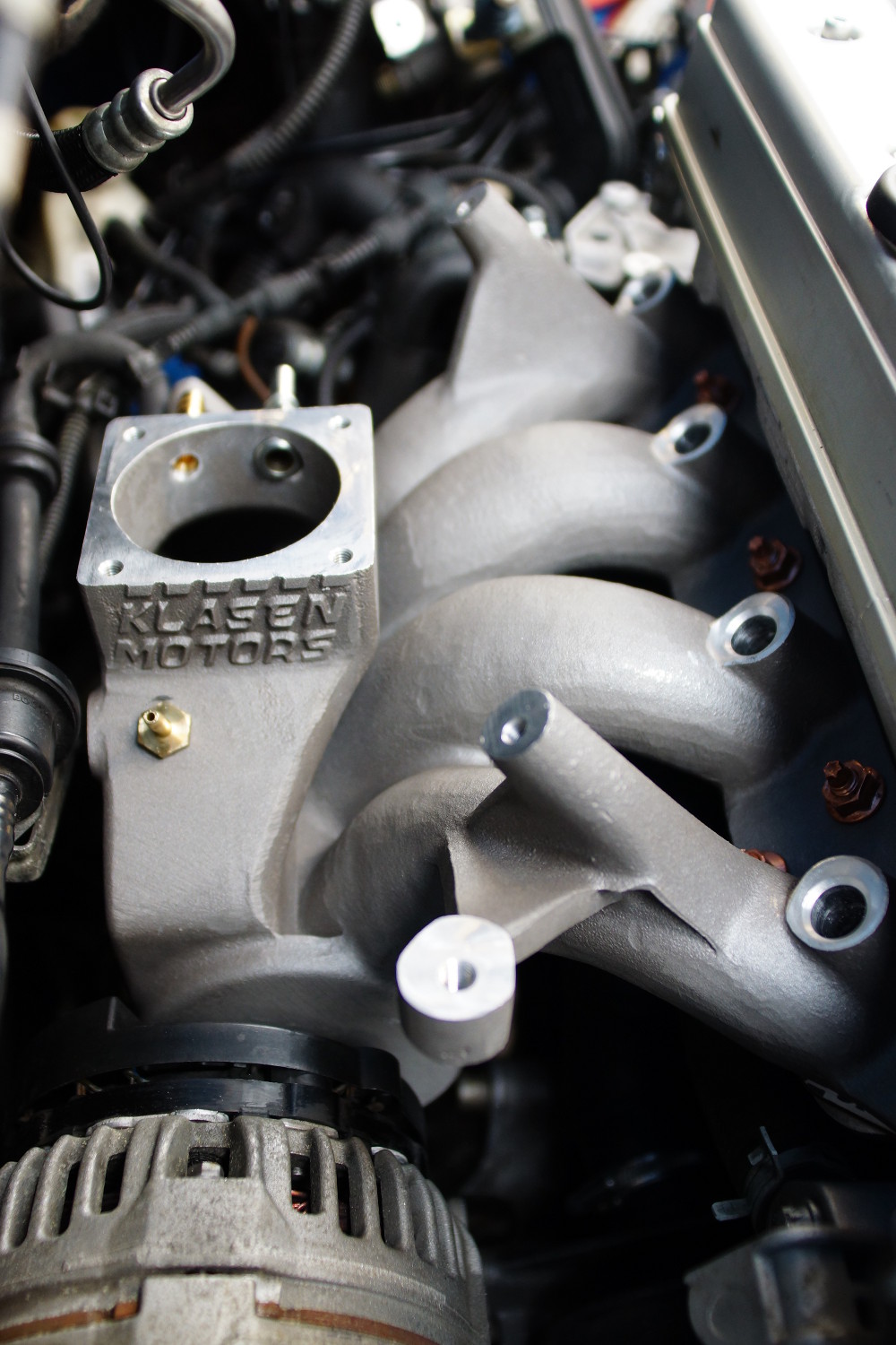
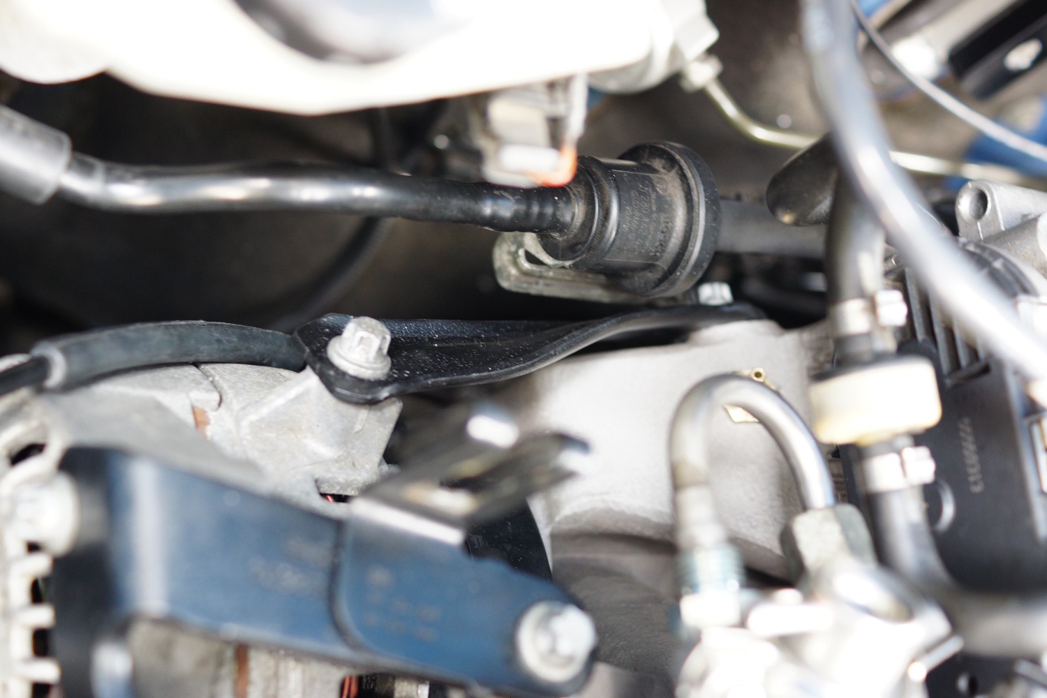
Fitting for the Gearbox Oil Temperature Sender, which is a Speedflow fitting (M18x1.5 to ⅛th NPT) sourced from Australia. This is located into the front of the gearbox where the level check plug would otherwise be, and will be fitted with a new sealing washer supplied with the fitting:
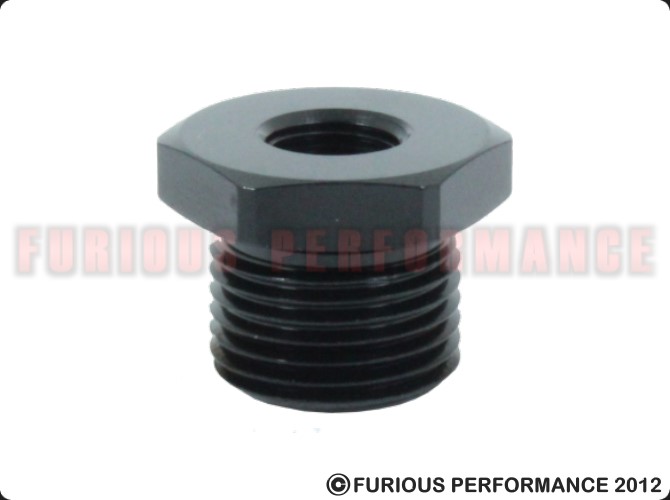
M18x1.5 to ⅛th NPT Adapter
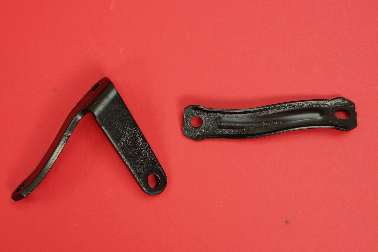
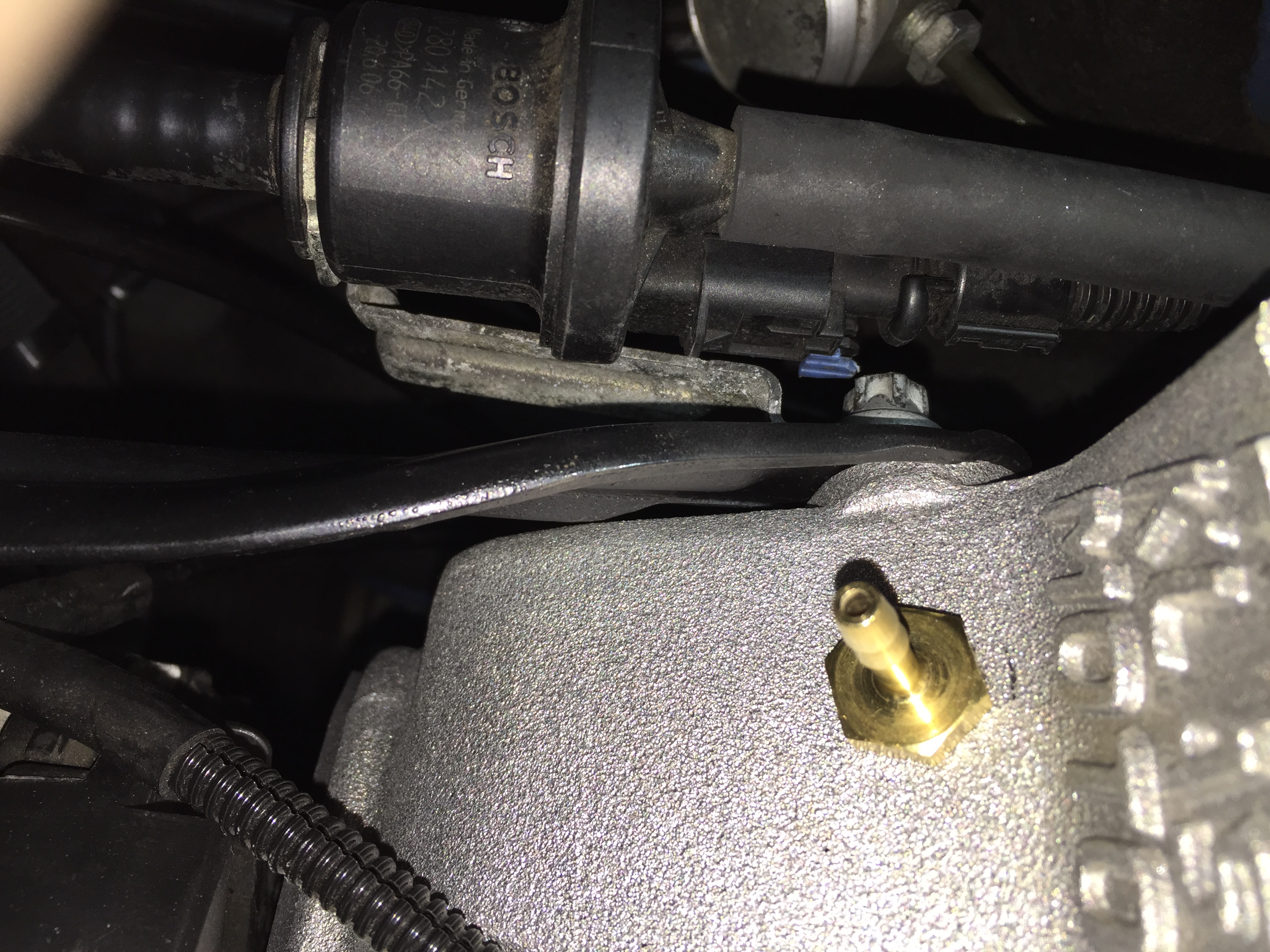
Sender Units installed into fittings (engine oil – left, gearbox oil – right):
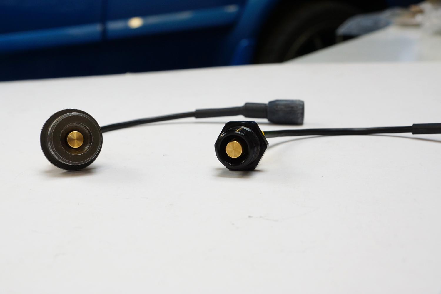
Senders Installed into Fittings
Gearbox Oil Temperature Sender:
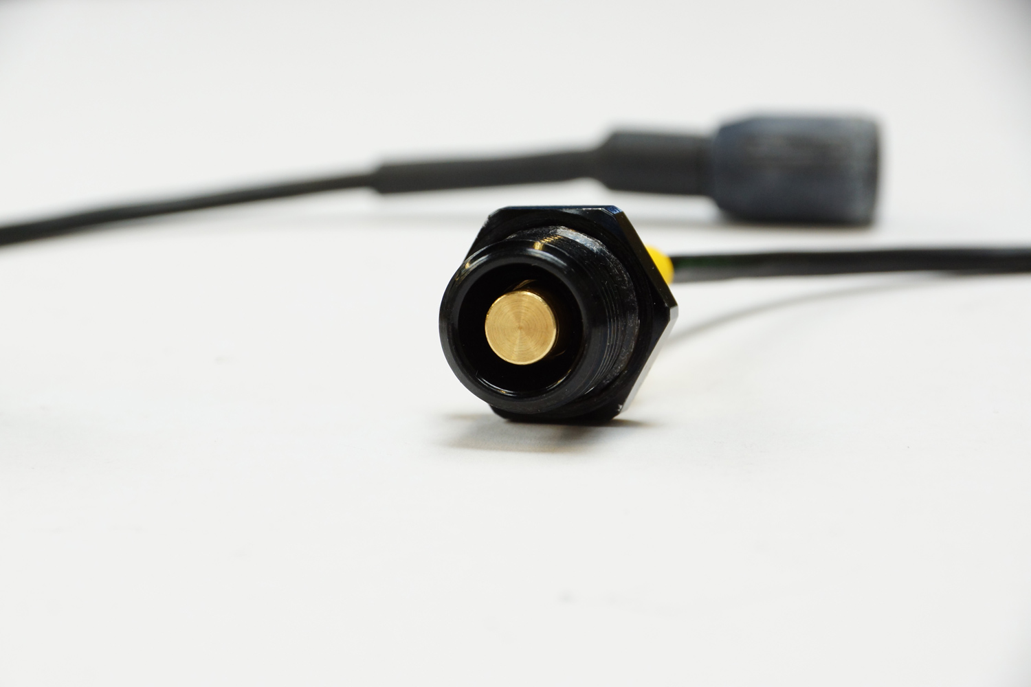
Gearbox Oil Temperature Sender
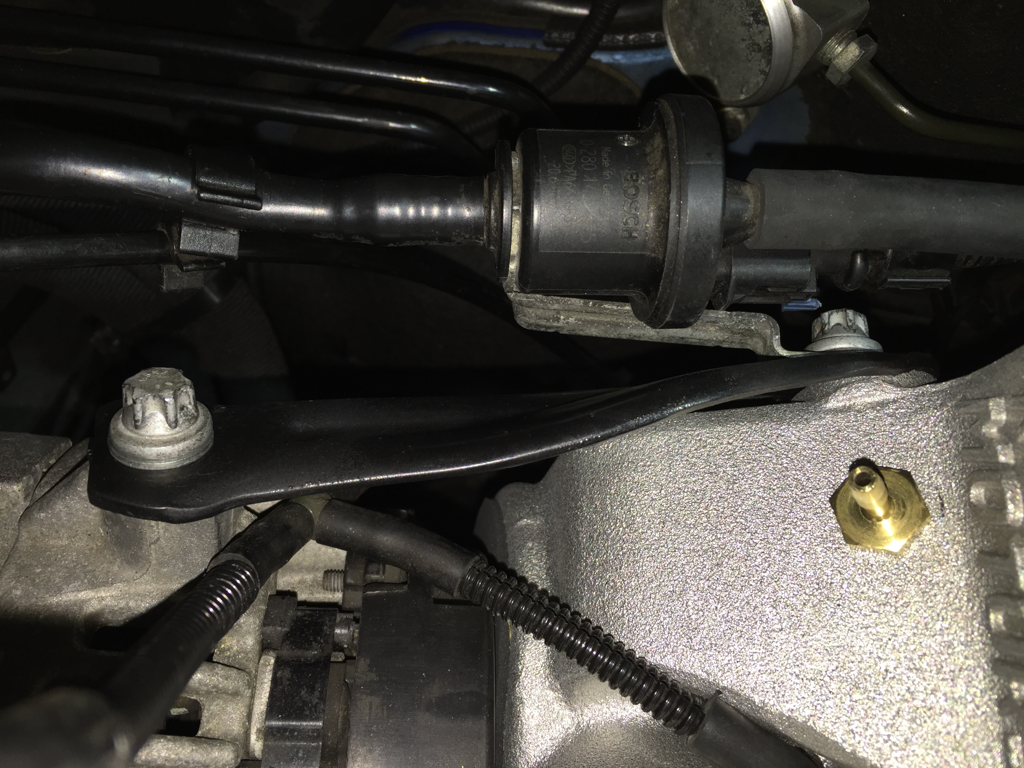
Engine Oil Temperature Sender:
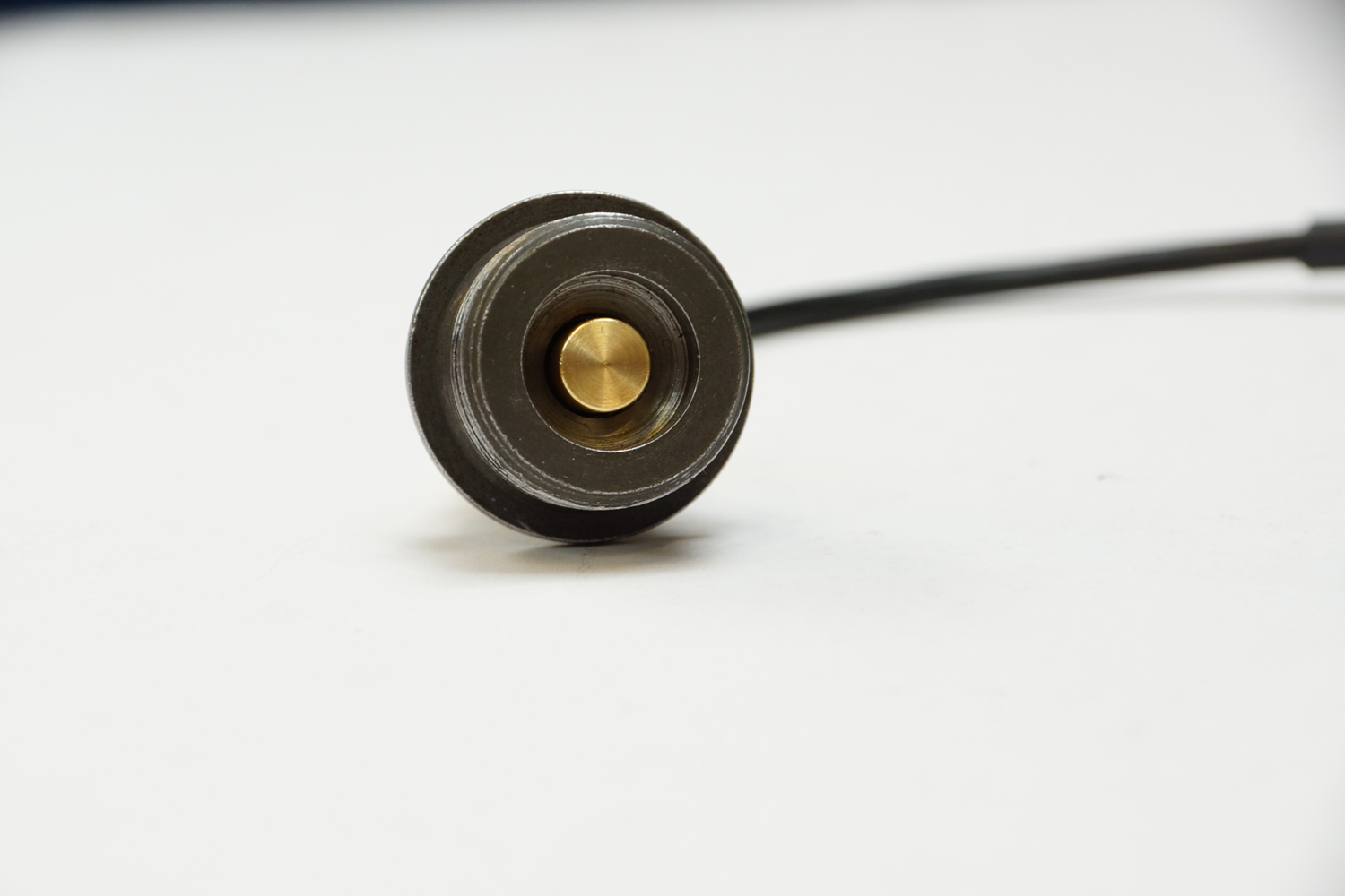
Engine Oil Temperature Sender
Next was the issue of where to mount the gauge. So a dual gauge facia (front for a vent pod) was bought from ebay for the SPA Gauge and the Boost Gauge which is designed to sit in the right hand air vent.
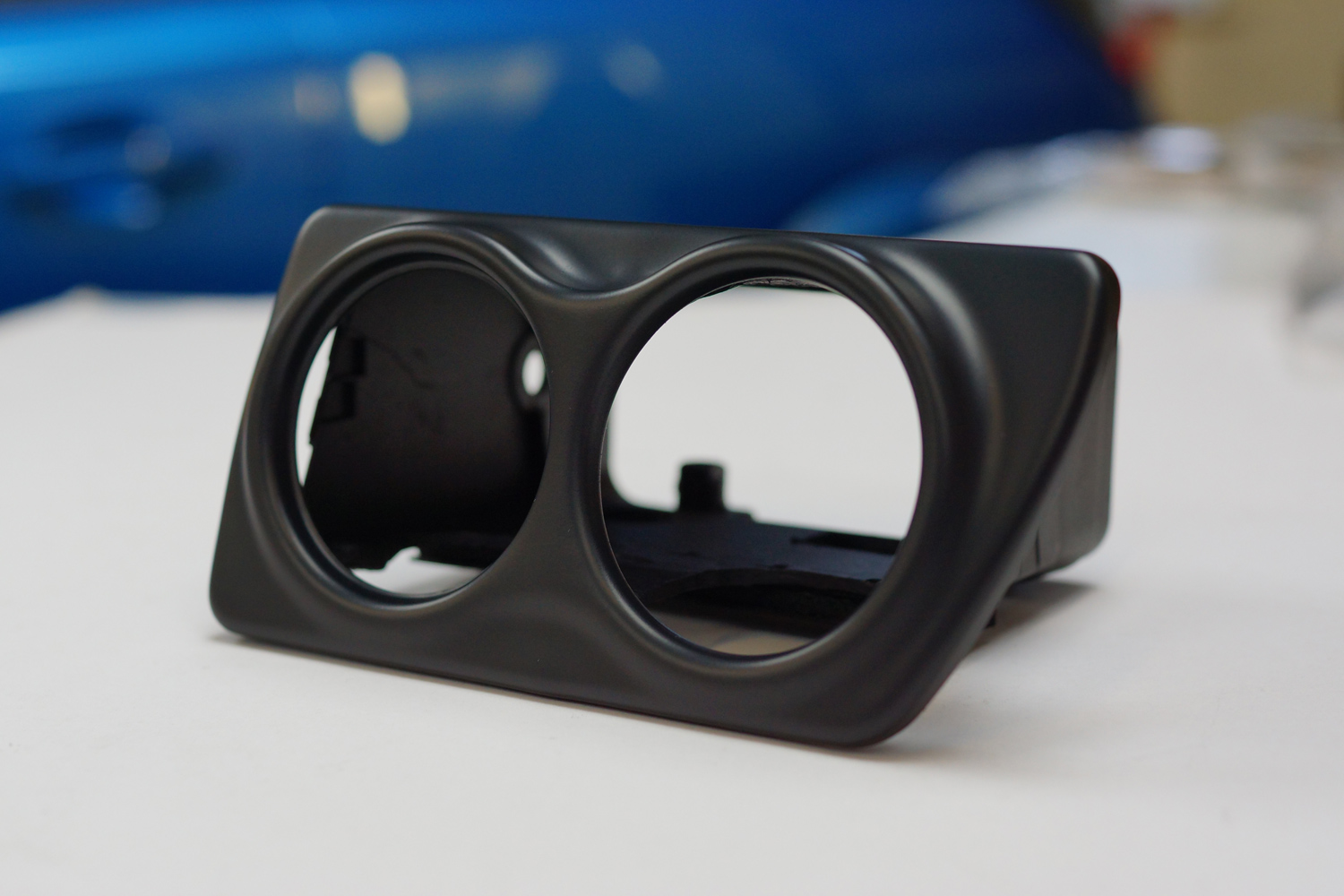
I then set about modifying the right hand air vent housing to accept the facia. Several hours of cutting and shaping with a multi tool later and the facia was bonded to the housing. The supplied facia is gloss black:
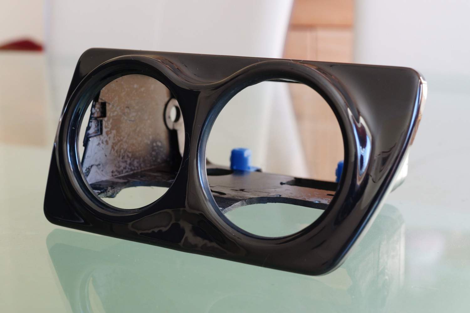
Dual Gauge Pod
And from the rear with two OE plastic captive nuts to allow the complete assembly to be held into the car securely:

Dual Gauge Pod – Rear
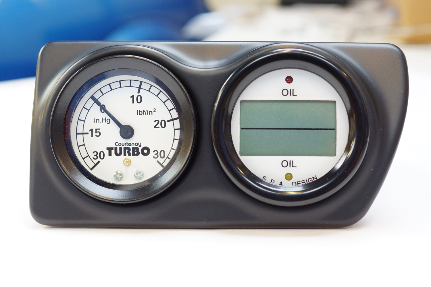
Not happy with the gloss black finish the facia was prepped and sprayed in Matt Black:
Dual Gauge Pod – Satin Black
And with both gauges fitted ready to go into the car. The comprehensive wiring supplied with the SPA gauge means that the only connection into the gauge is a 12 pin multi plug, that simply plugs in, and the boost gauge has a vacuum/boost line run to it from the engine (fuel pressure regulator vacuum pipework) and an illumination feed for when the headlights are on to illumine the gauge. This feed was run into the car from the feed to the side light from the right hand headlight loom as a 12v feed is needed (the bulb in the gauge is 12v):
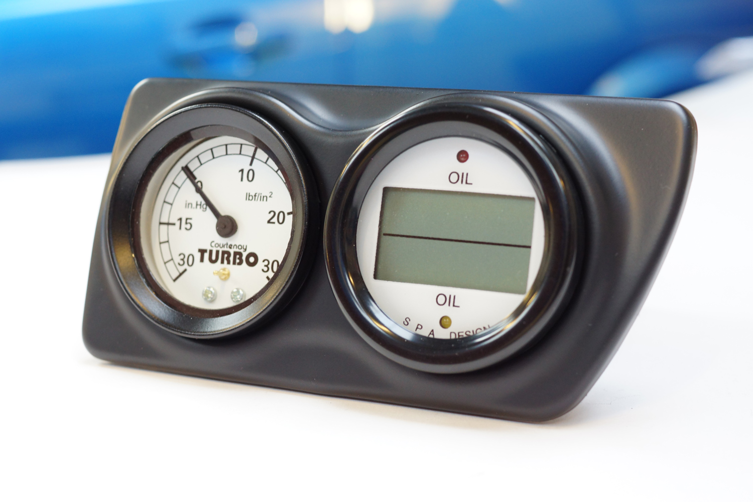
Gauges Installed
Gauges Installed
Picture from under the dash showing the retaining screws (just visible centre and top left) secured through the original air vent plastic pipework and into the captive nuts in the gauge pod, which all one up when the gauge pod is pushed fully home:
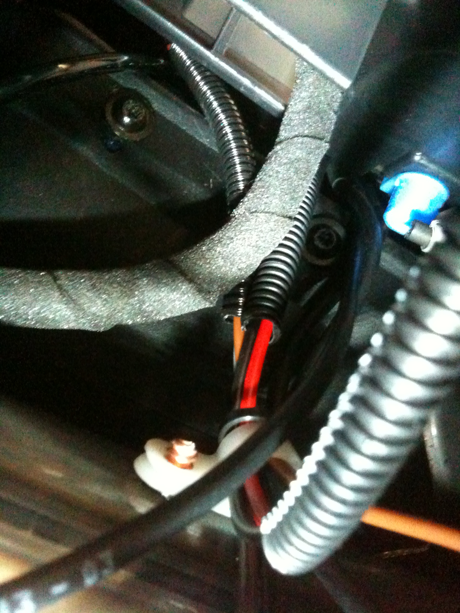
Retaining Screws
Gauges installed and functioning. Boost Gauge (Left) and Dual Oil Temperature Gauge showing the Engine Oil Temperture (Top) and Gearbox Oil Temperature (Bottom. The functions and settings for the SPA gauge are controlled by the red push button mounted on the steering cowl, visible bottom left of picture:
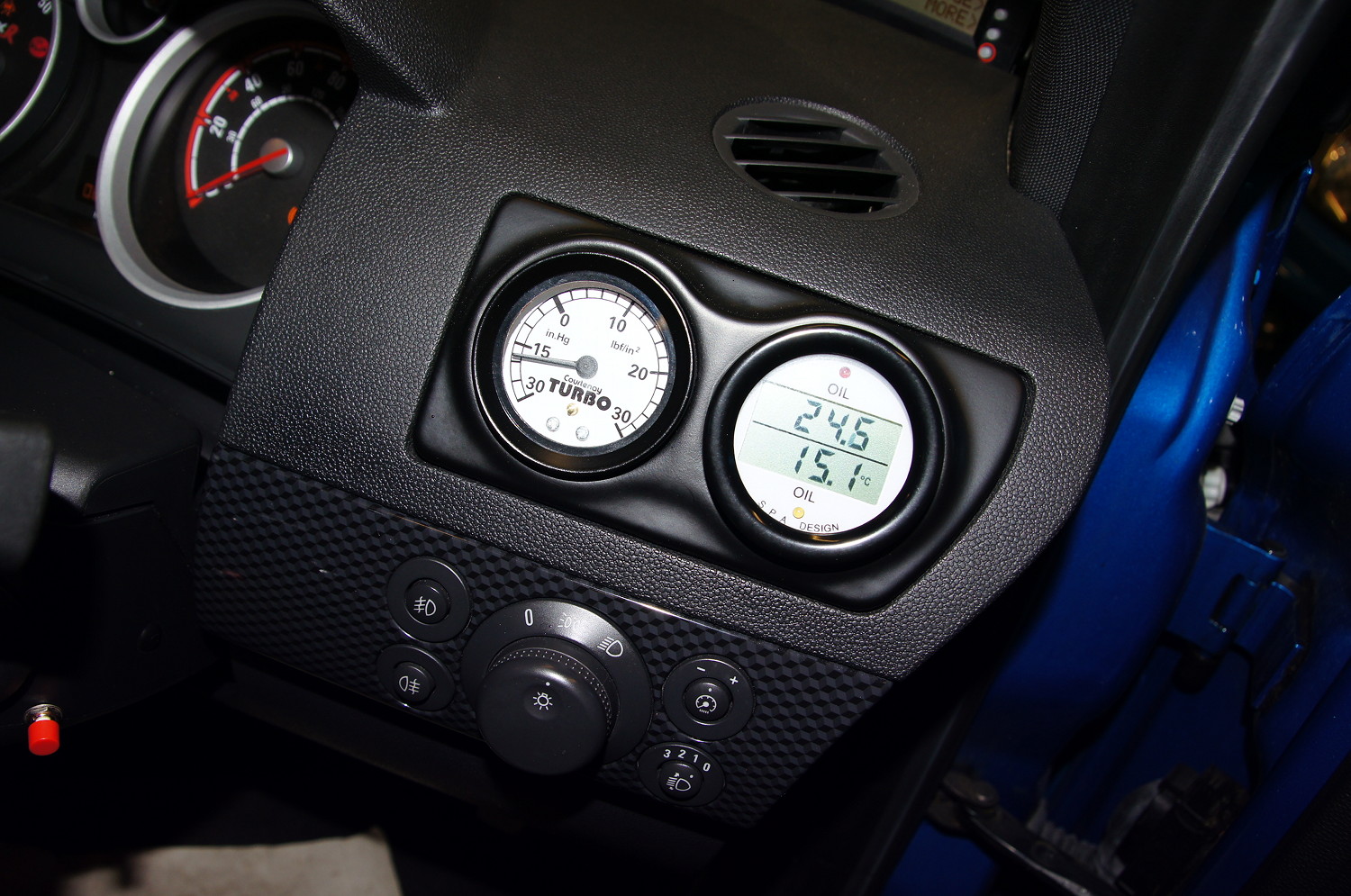
Gauges Installed