Intercooler and Water Radiator
- Jun 25th. 2012
- By mapw
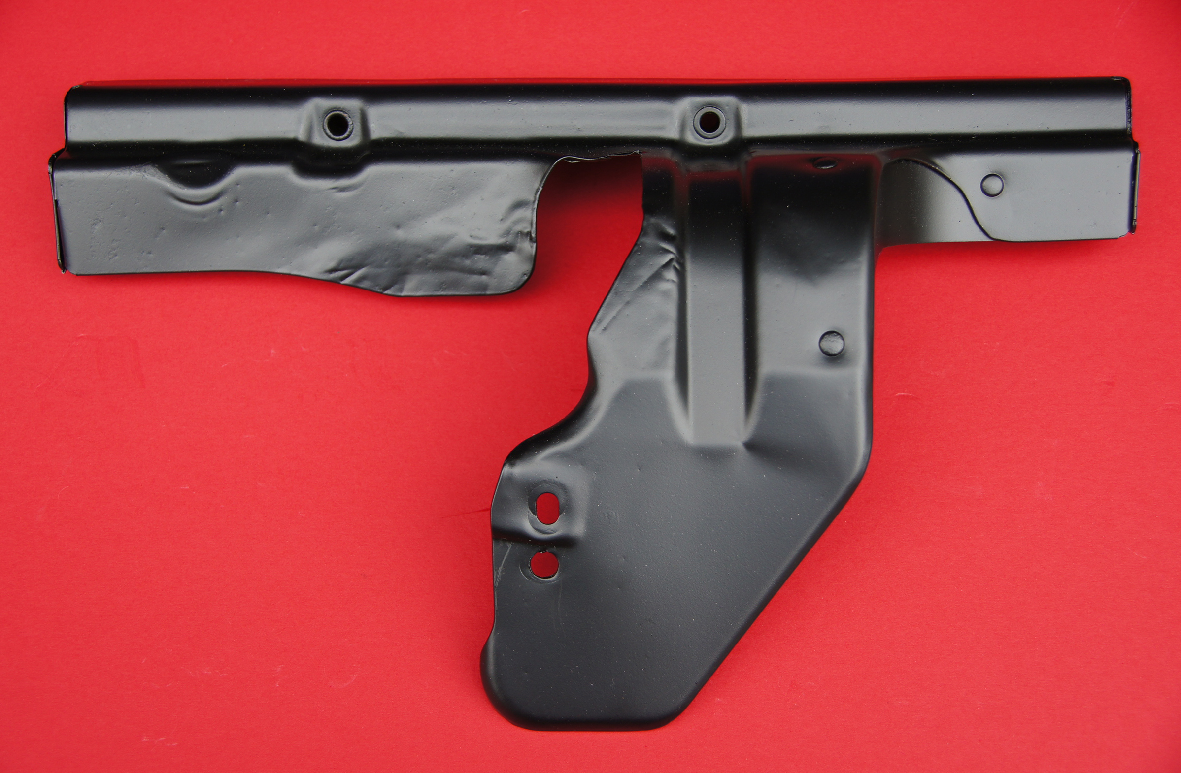
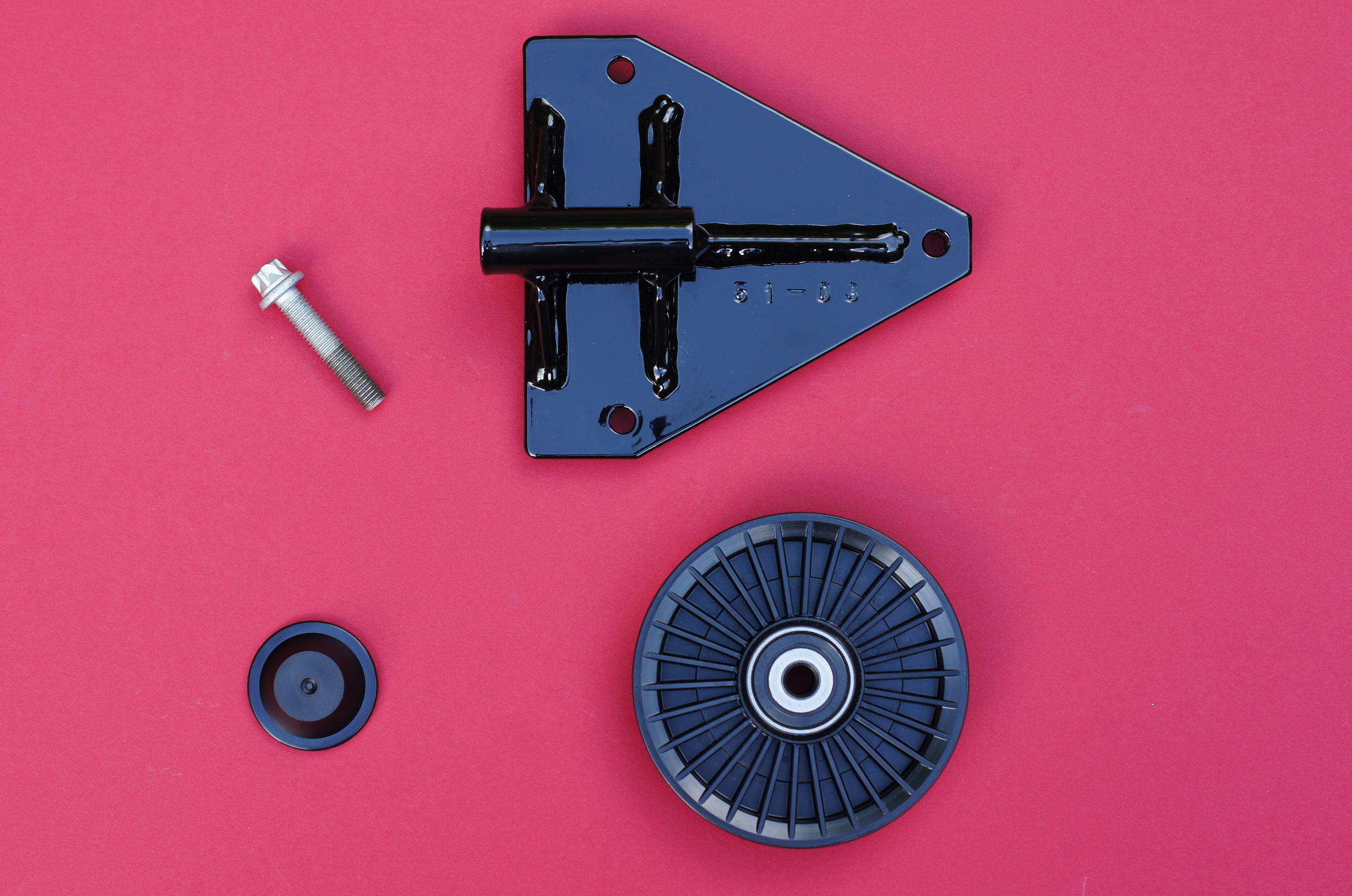
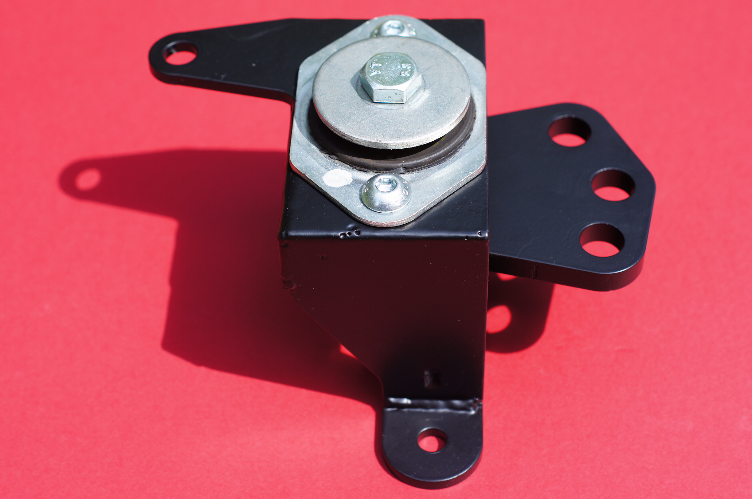
The OE radiator lower support brackets (minus rubber inserts – top) and the Pro Alloy Intercooler mounting brackets (bottom) have had a fresh coat of paint to tidy them up.
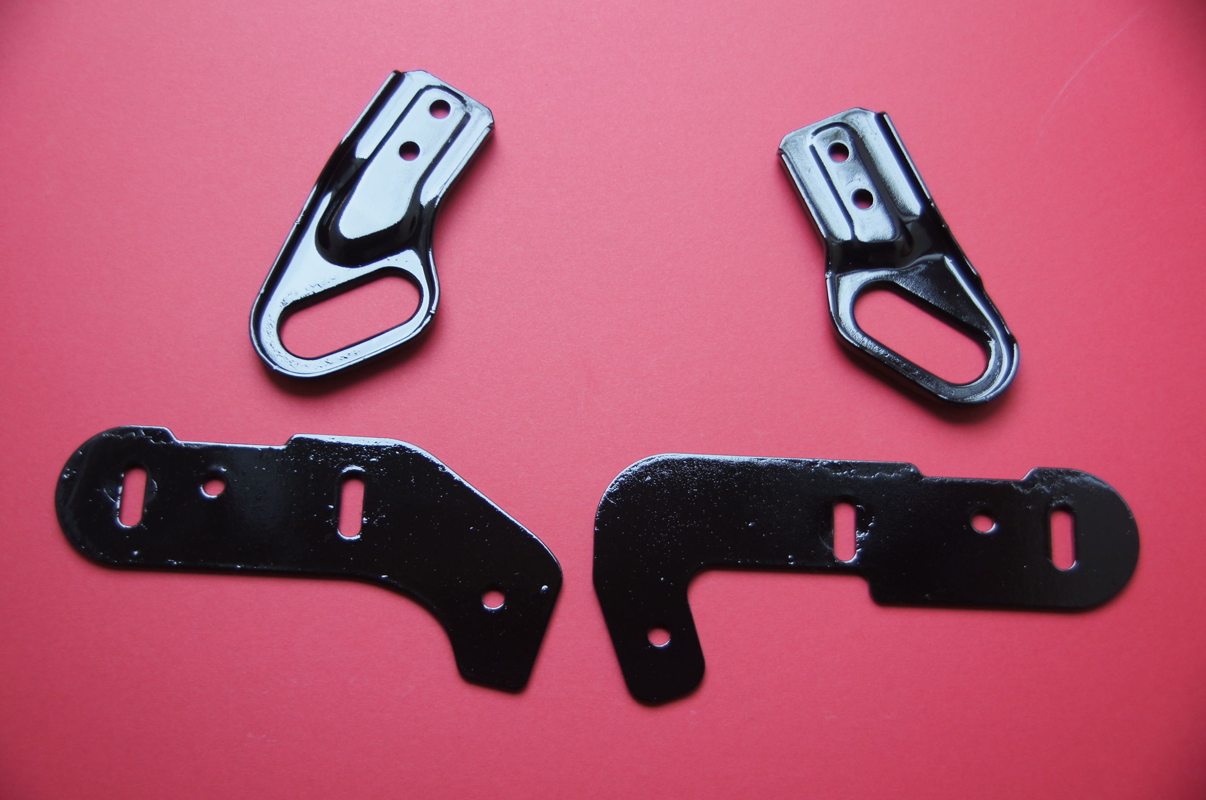
Radiator and Intercooler Brackets
Pro Alloy Intercooler (in Stealth Black finish) returned from Pro Alloy after having had the outlet (right hand top) opened up to 60mm from 50mm, plus the addition of a 60mm outlet pipe with map sensor boss (not shown).
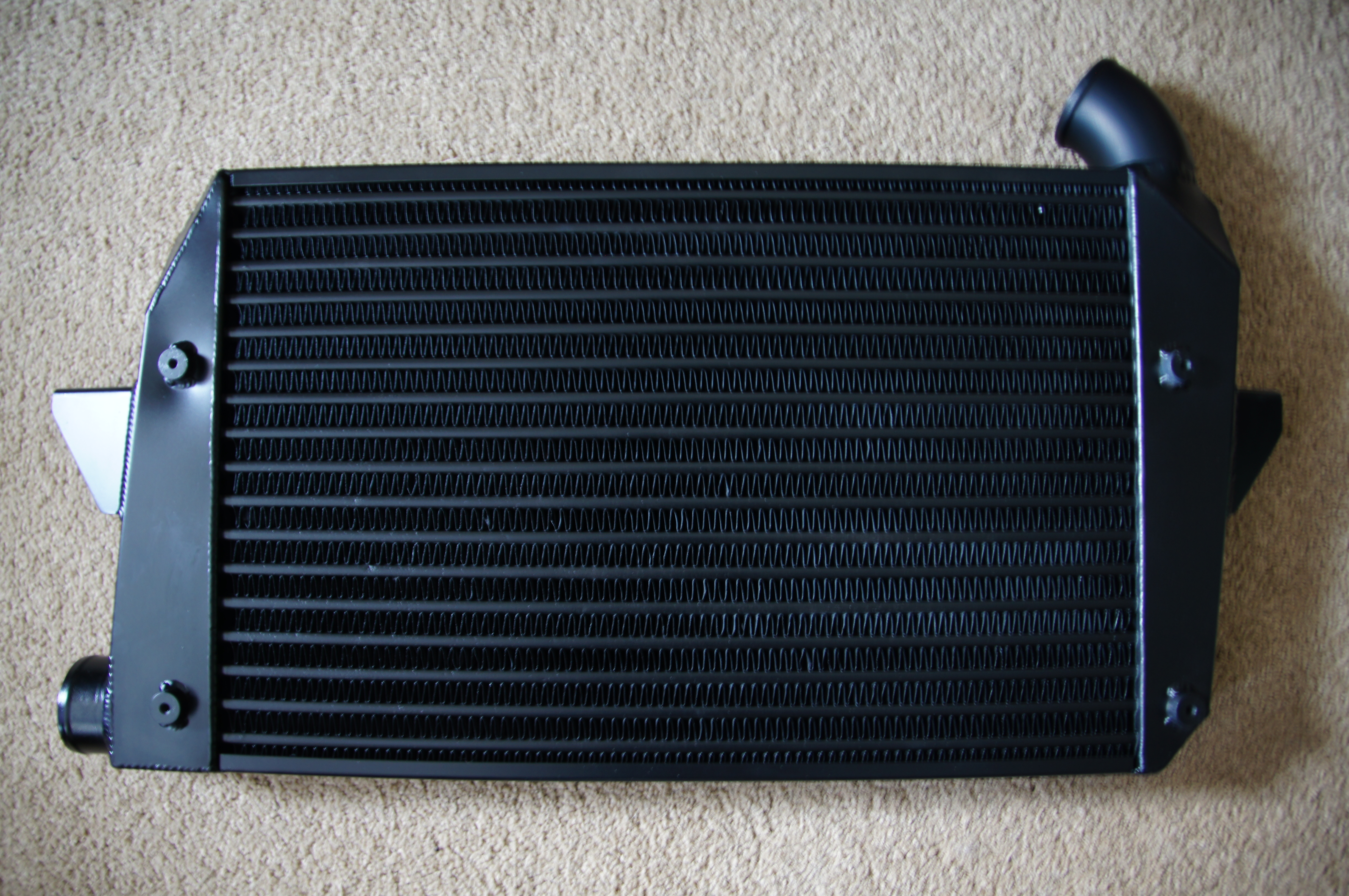
Pro Alloy Intercooler
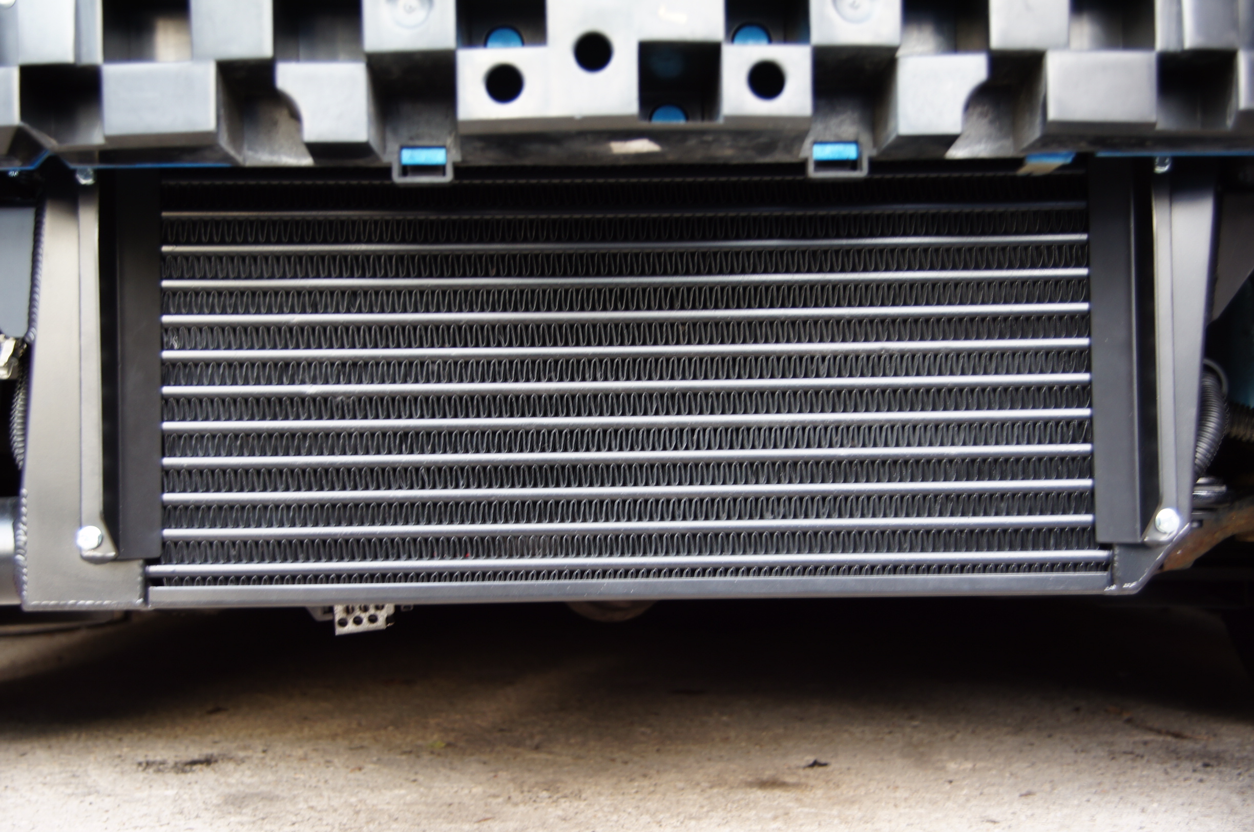
New Pro Alloy Water Radiator, in Stealth Black finish.
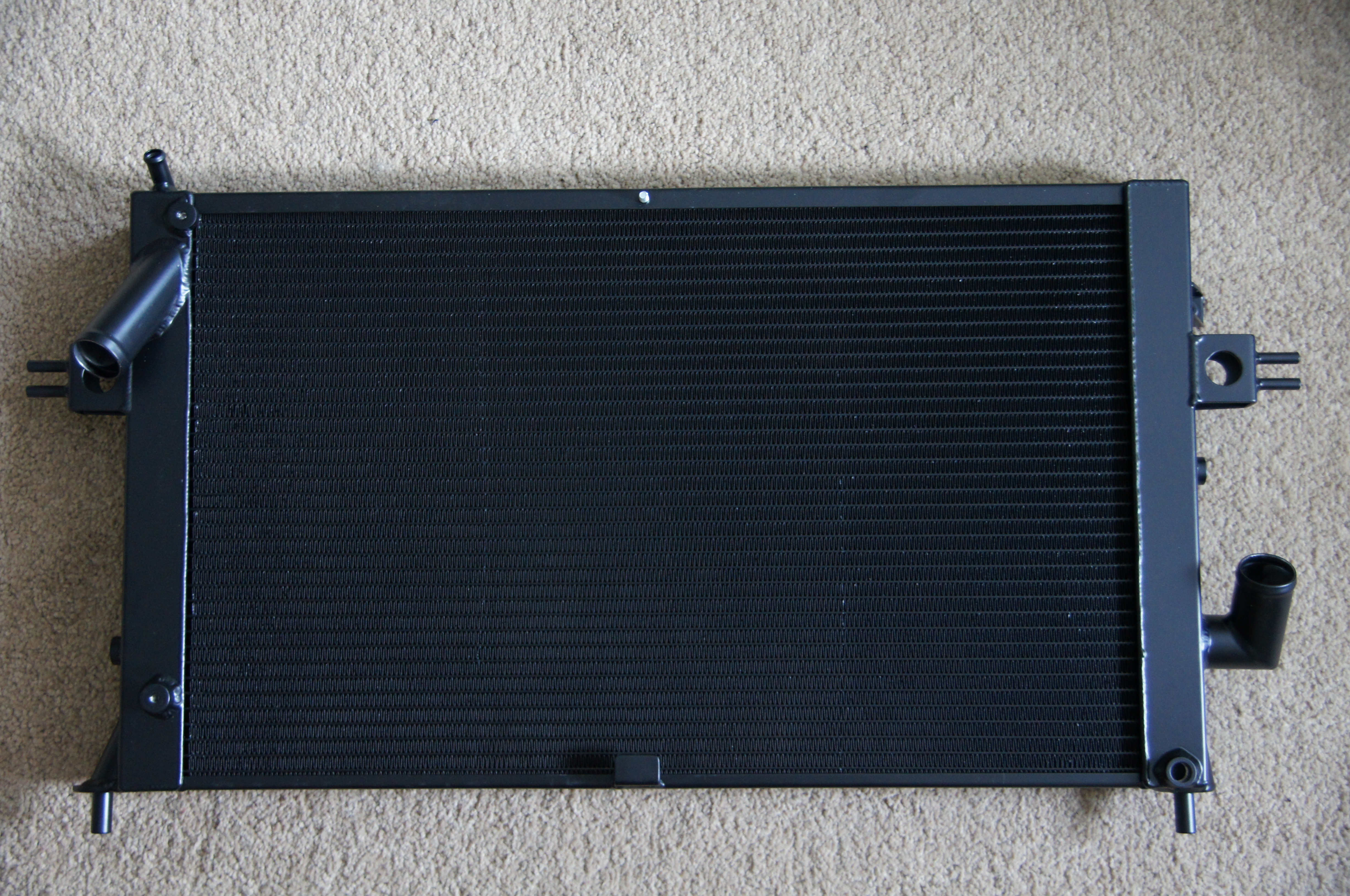
Pro Alloy Water Radiator
Black Intercooler Hoses to replace the original blue hoses, plus black alloy 90 joiner pipe (top left).
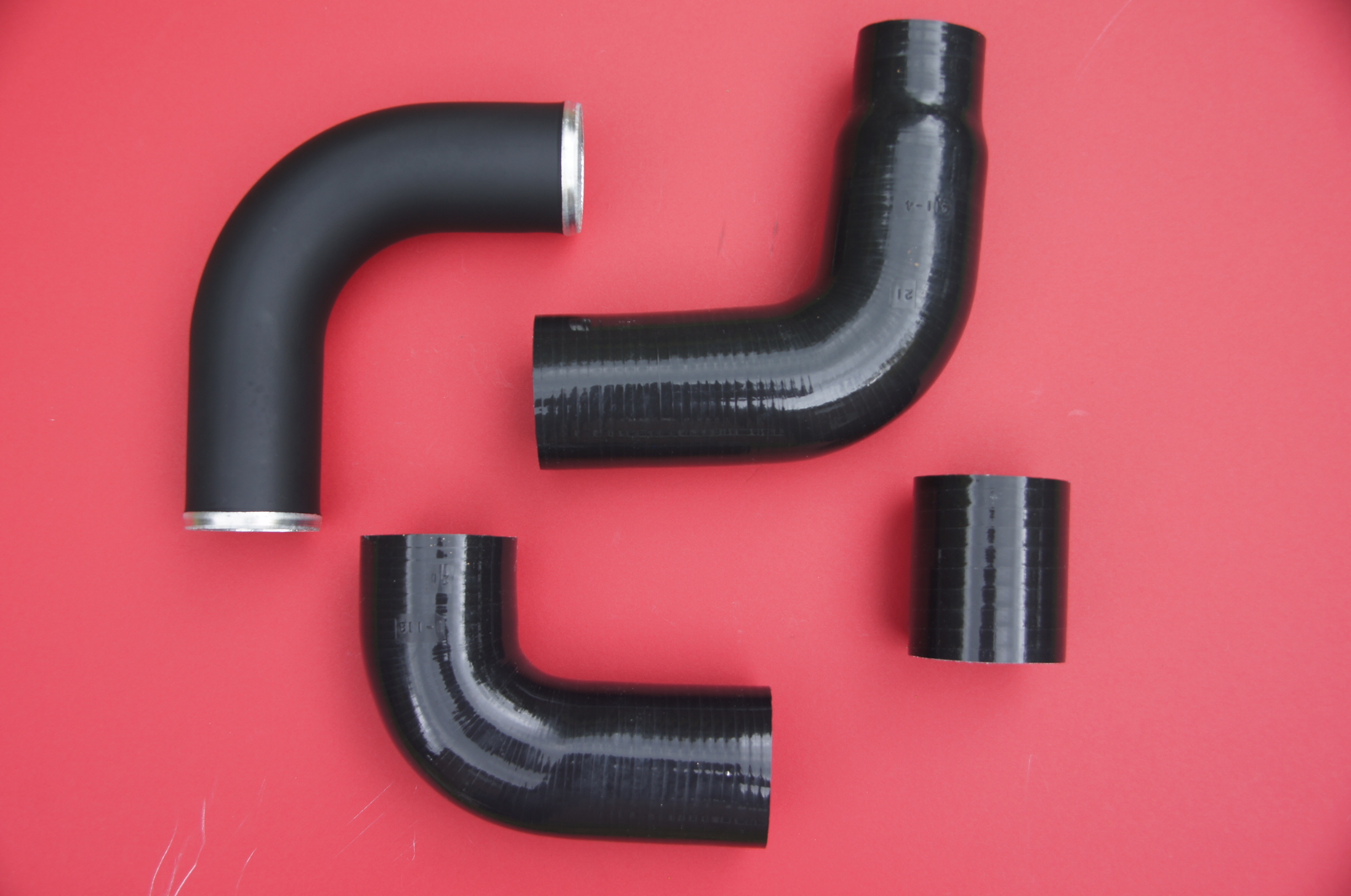
Intercooler Pipework
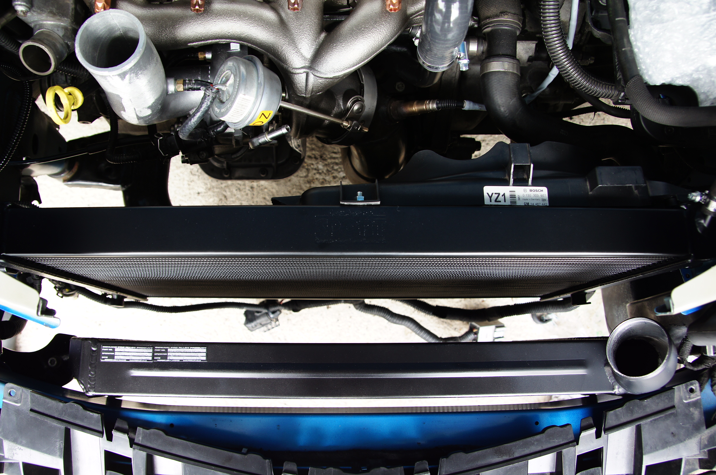
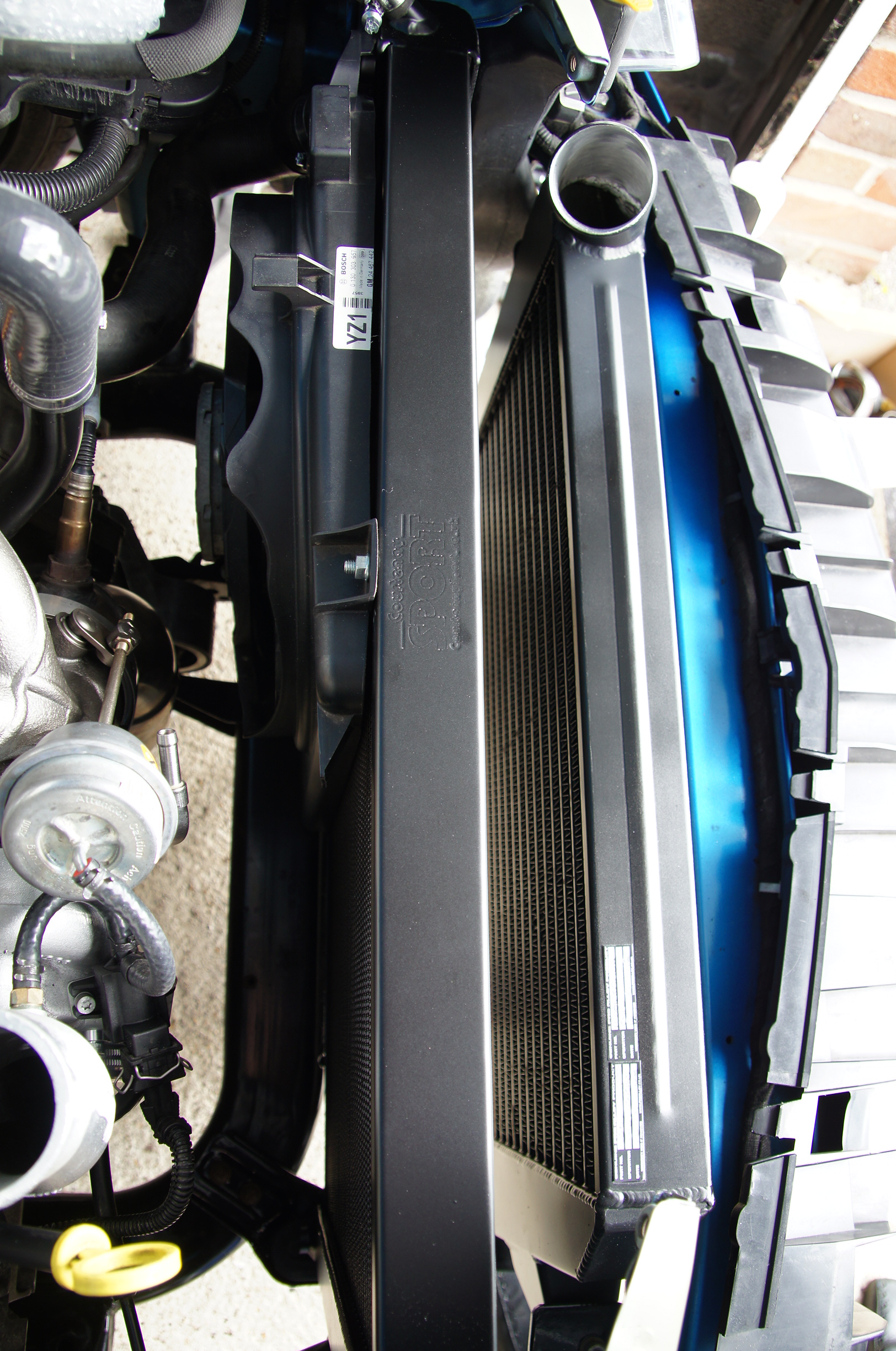
Water Rad fitted.
Water Rad Fitted
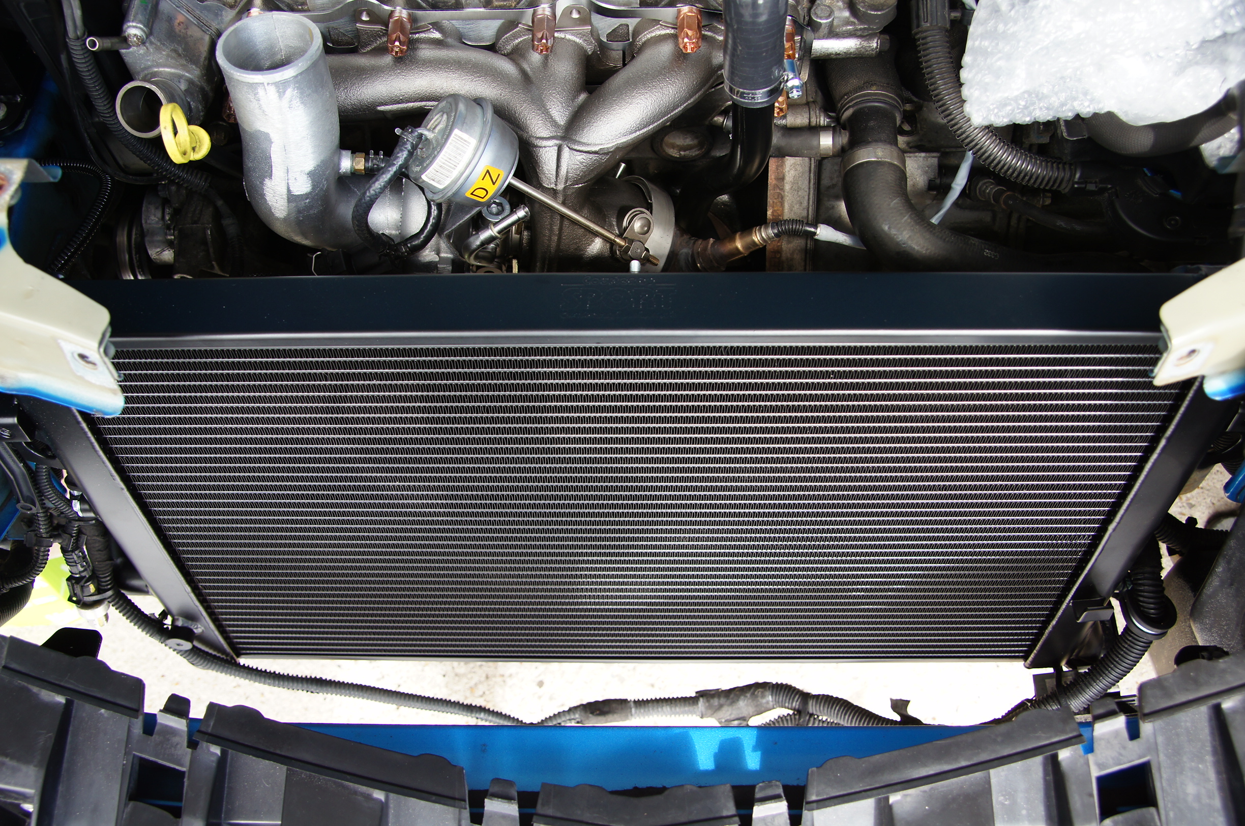
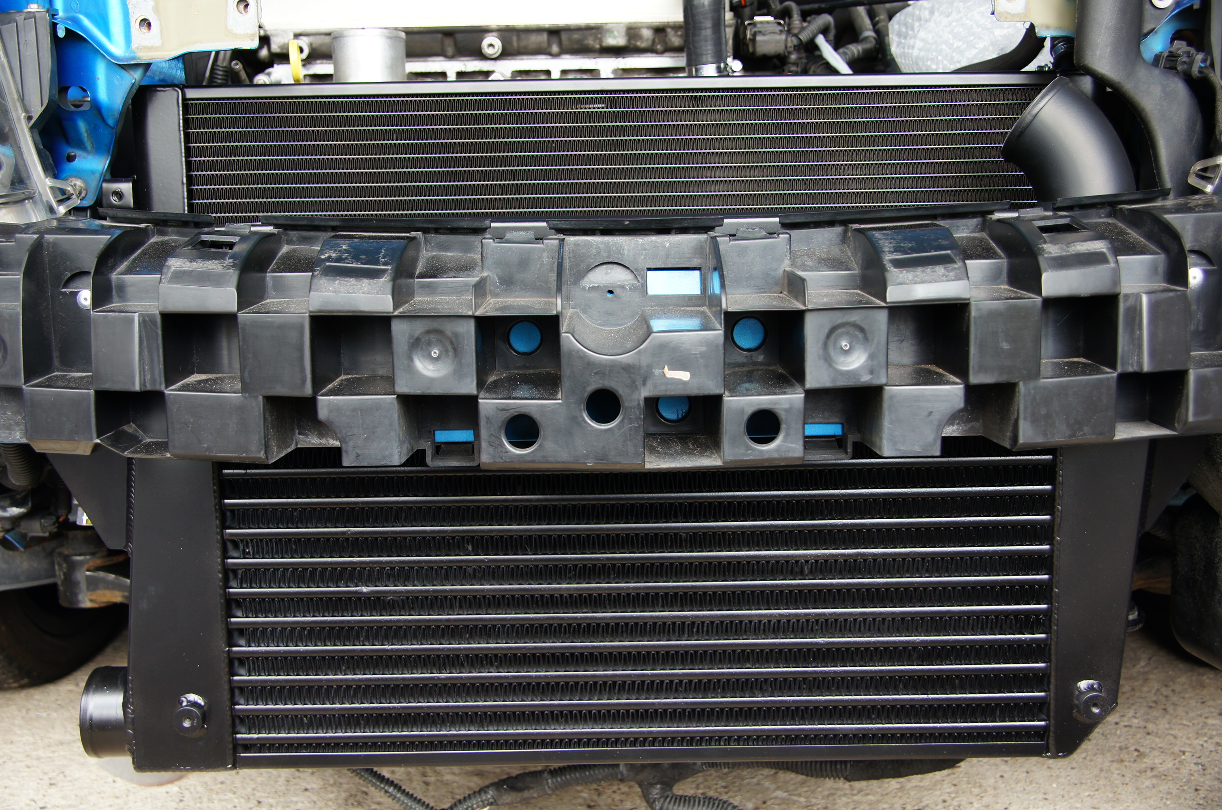
Water Rad and Intercooler fitted.
Water Rad and Intercooler Fitted
Water Rad and Intercooler Fitted
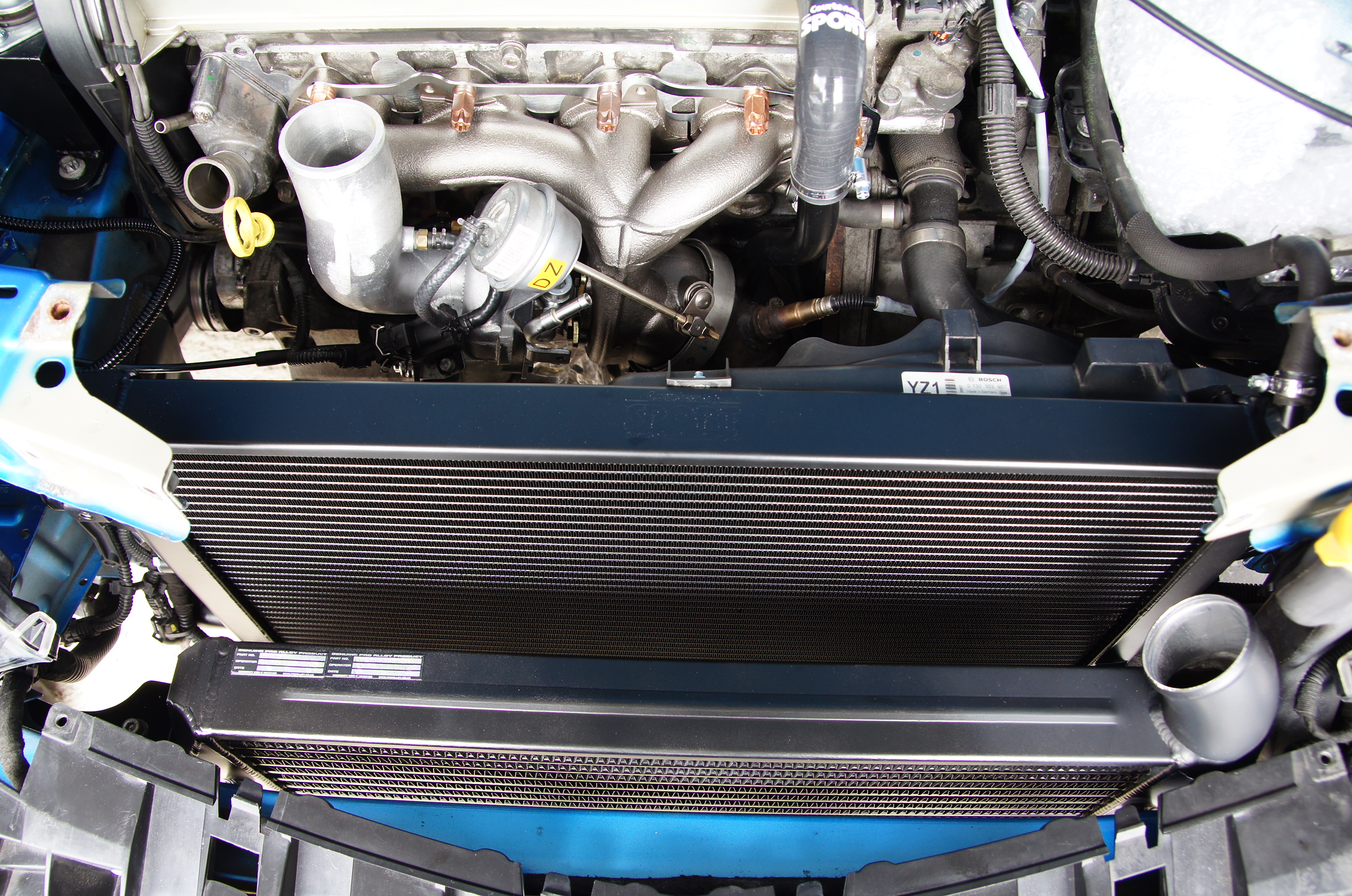
Water Rad and Intercooler Fitted
Intercooler
Track Spec Air Guide Blades added to the intercooler.
Intercooler Air Guide Blades
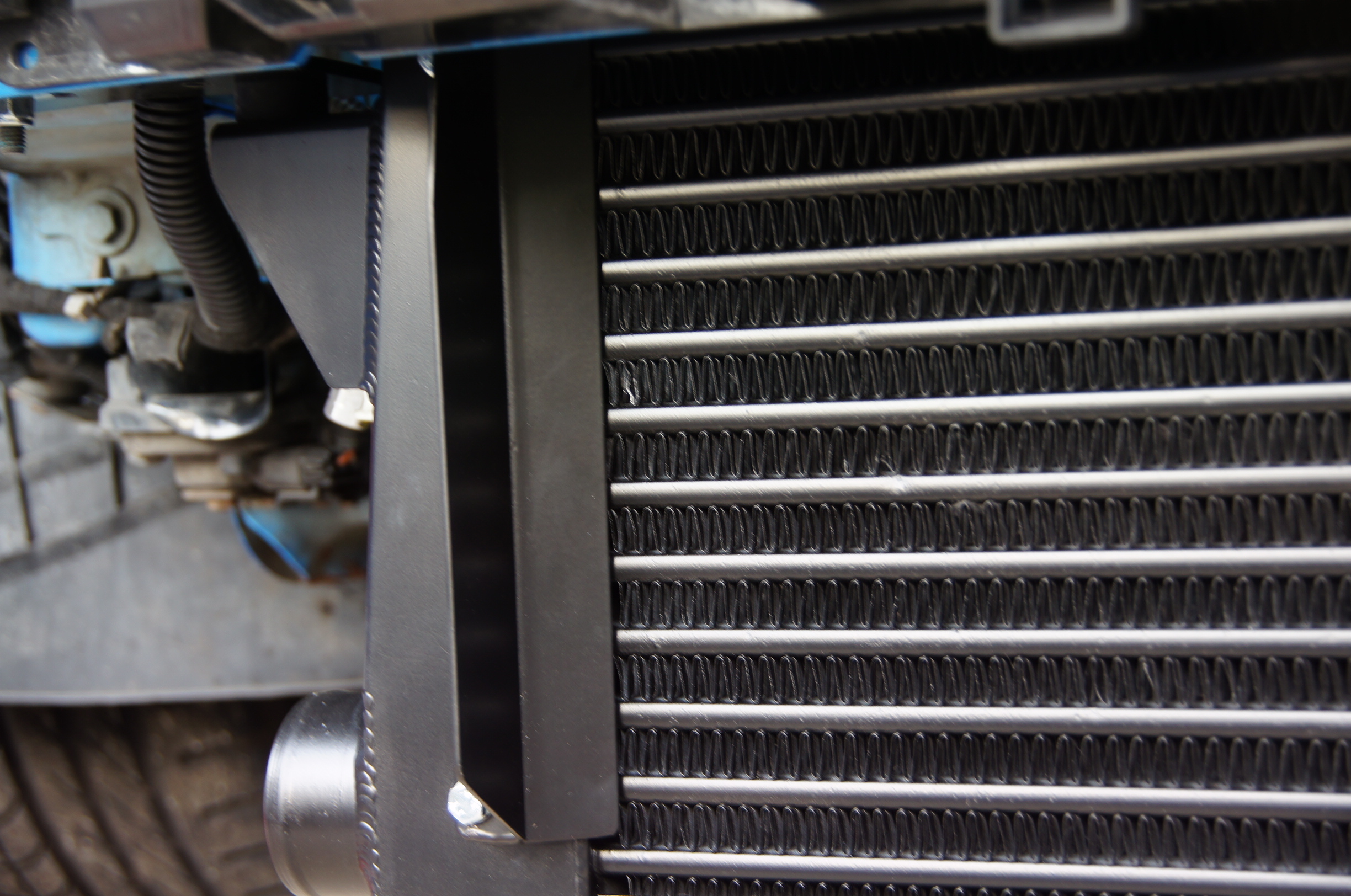
Air Guide Blade
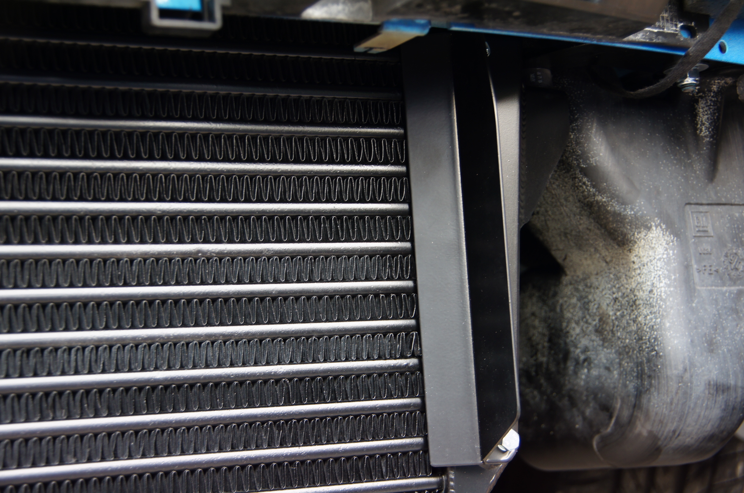
Air Guide Blade
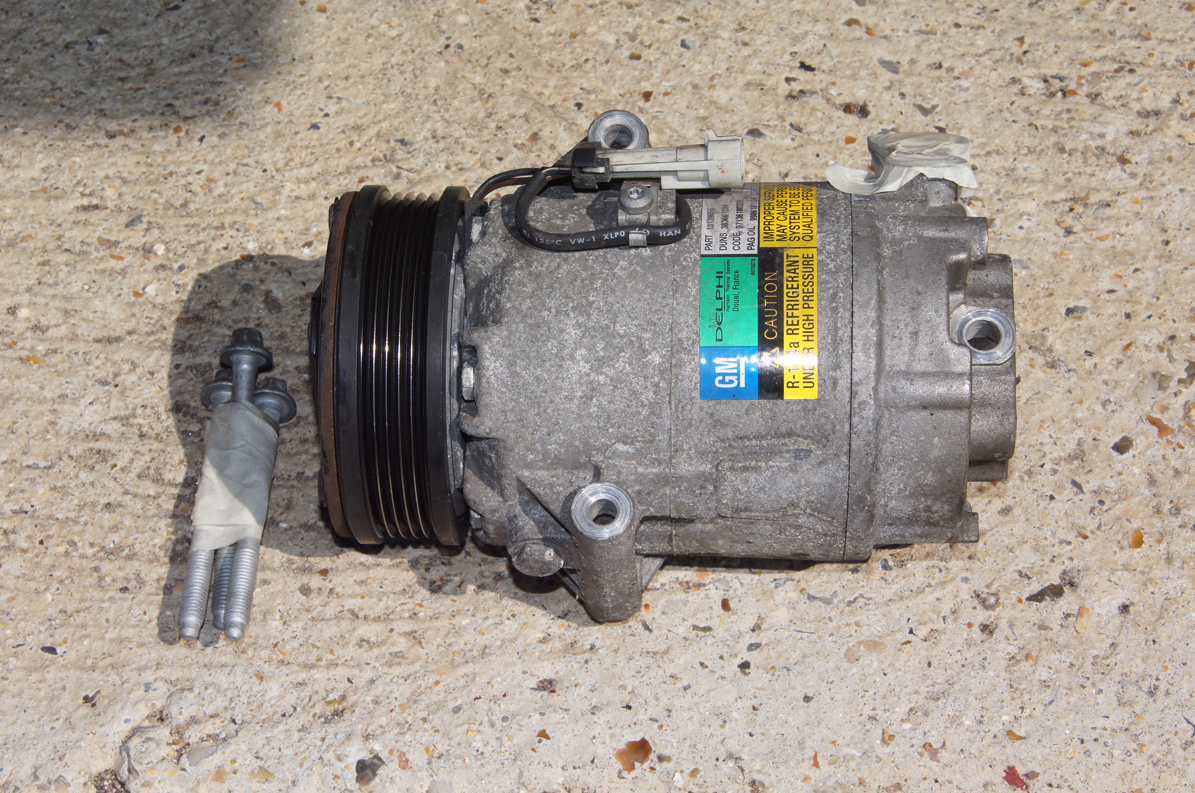
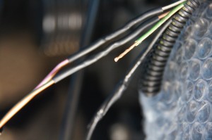
Fan Relays relocated to the water rad. They usually sit on a bracket on the front fan which sits on the air con condenser, which has all been removed for track work.
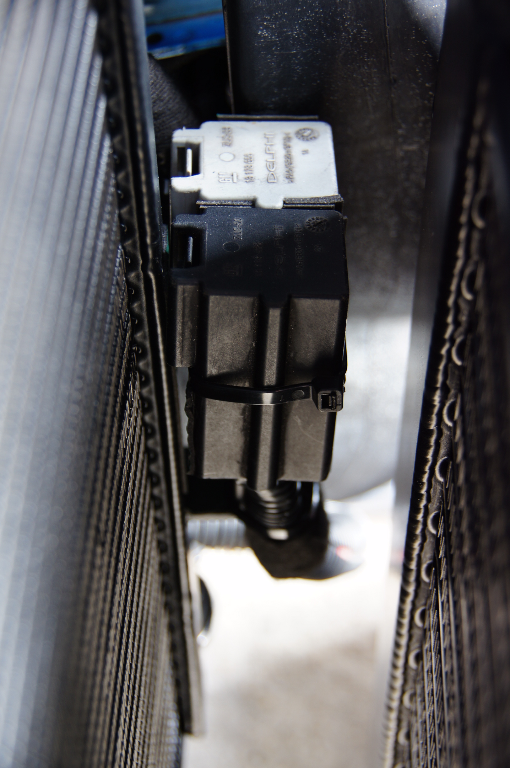
Fan Relays Relocated