Rear Brake Upgrade
- Aug 23rd. 2012
- By mapw
The rear brakes are being changed from the factory 278mm set up using solid discs to a larger 292mm set up using vented discs. This requires new callipers, discs, pads, mounting brackets and break lines. Additionally the rear calliper bodies are aluminium and lighter weight. The larger rear brake kit is being added because with good braking at the front end, the rear of the car tends to go ‘light’ under heavy braking. This larger brake set up helps add some additional braking to the rear end, helping the car to stay more level under very heavy braking.
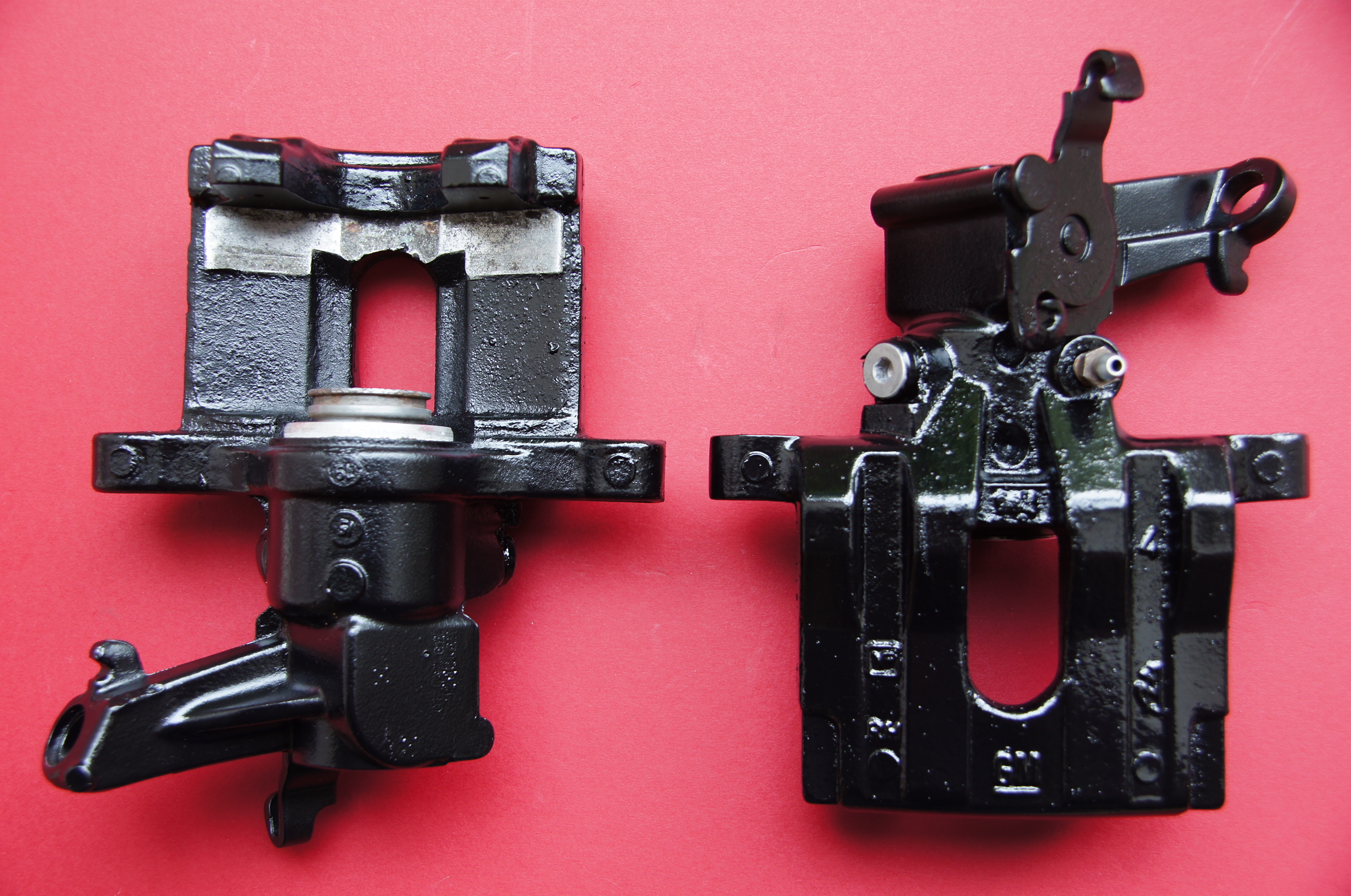
Rear Vectra C/Saab Calipers cleaned ready for paint. The brackets have been soaked in Bilt Hamber Deox-C to remove the rust and corrosion. The calipers have been manually cleaned of corrosion:
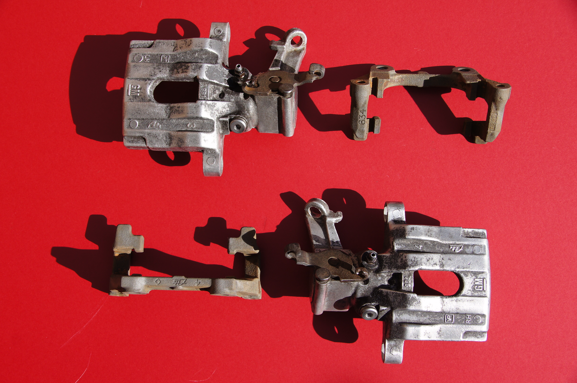
Rear Saab/Vectra C Calipers
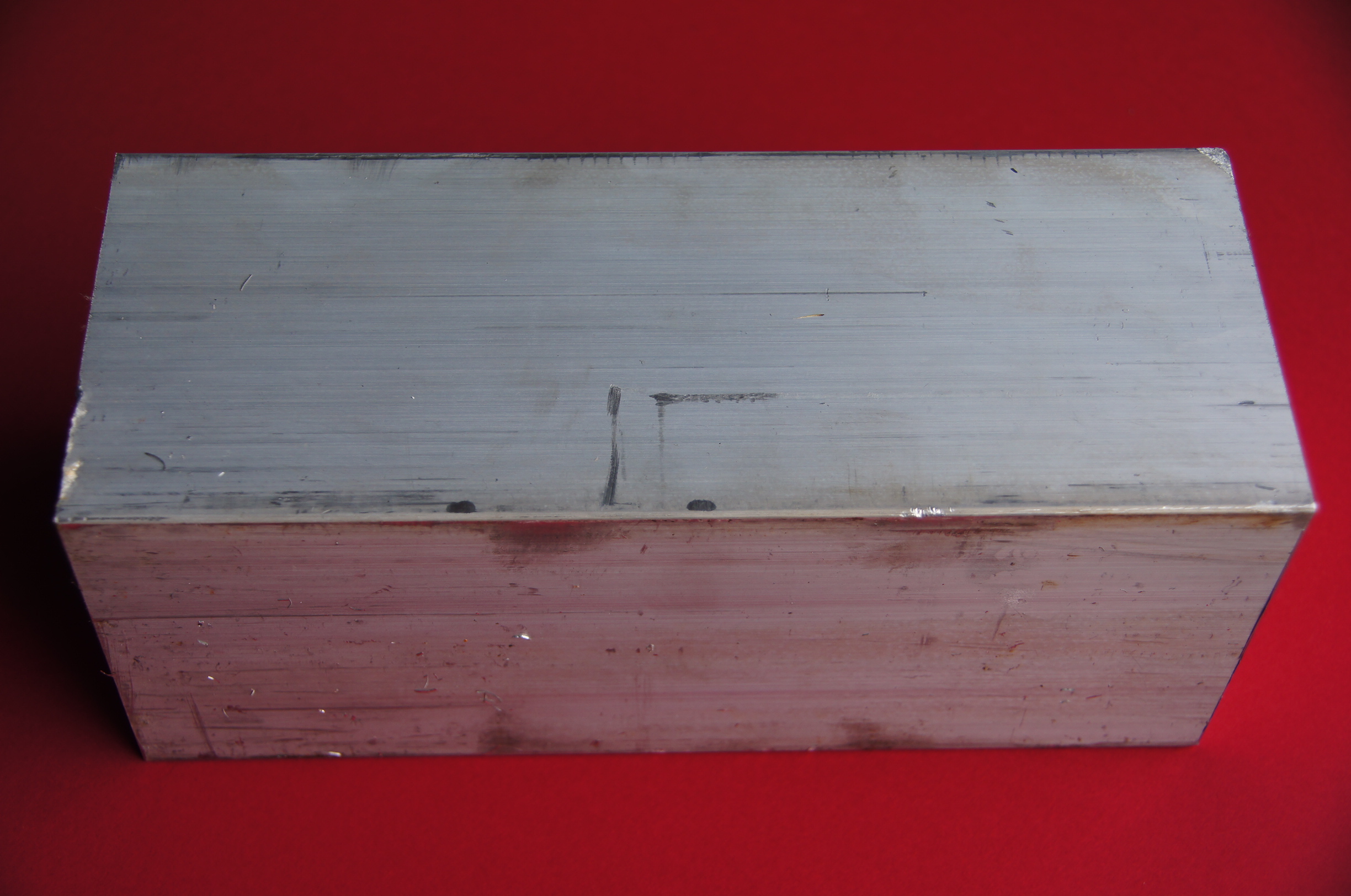
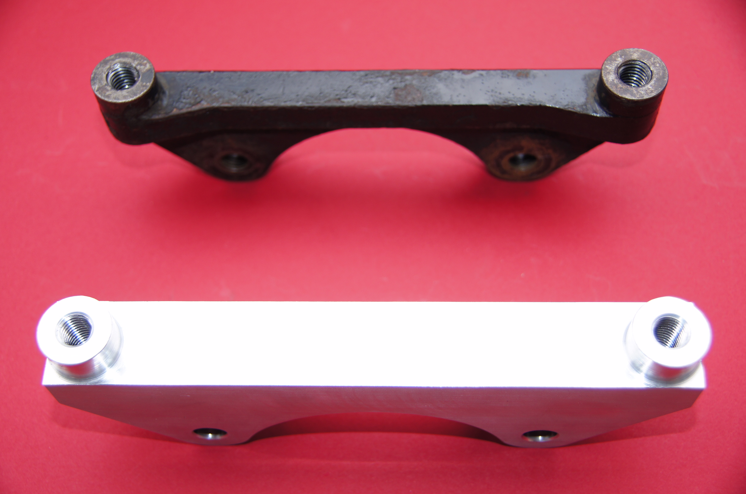
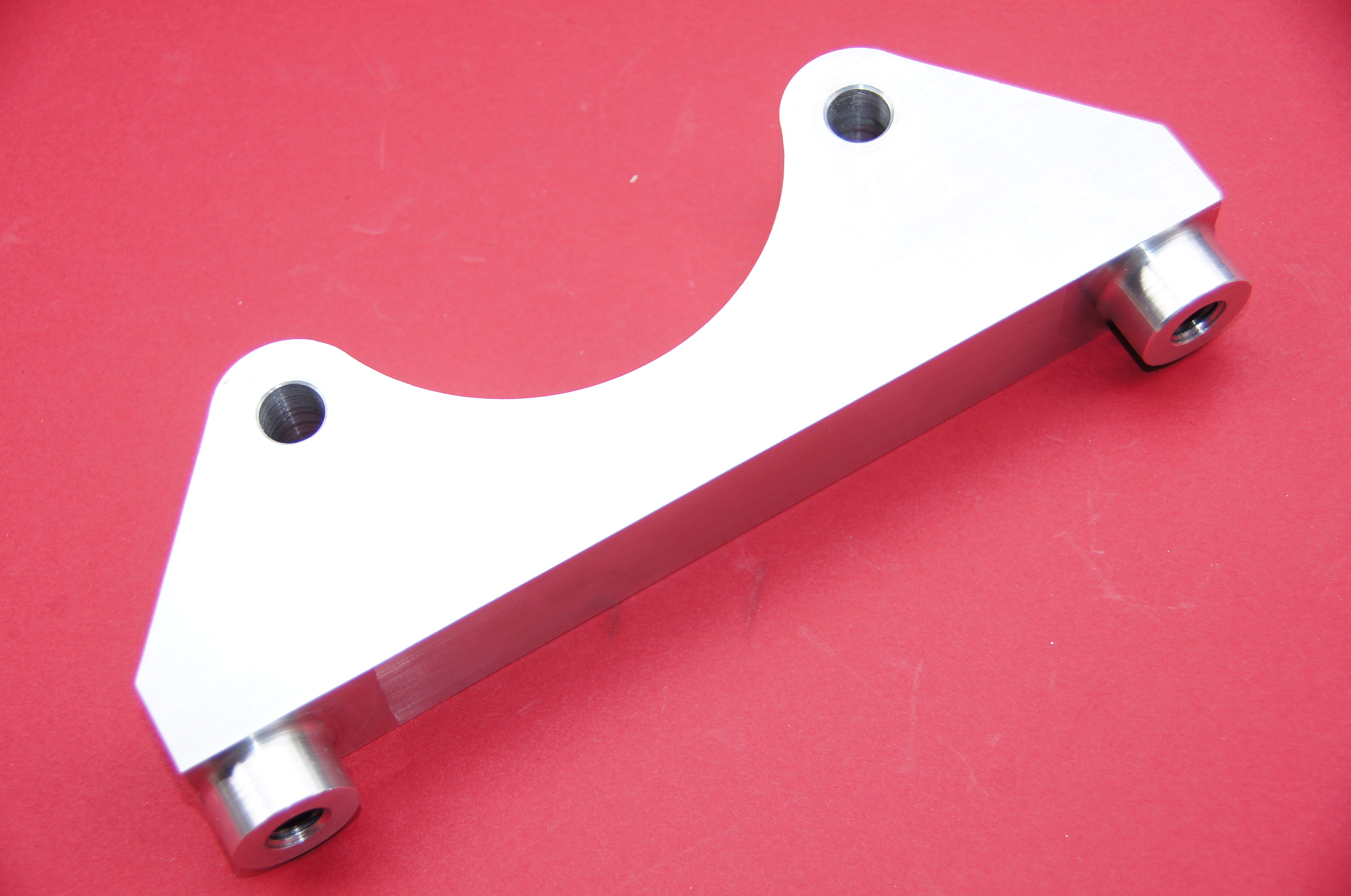
Rear CNC machined Mounting Brackets for 292mm Vented Brake Upgrade and Braided Brake Lines:
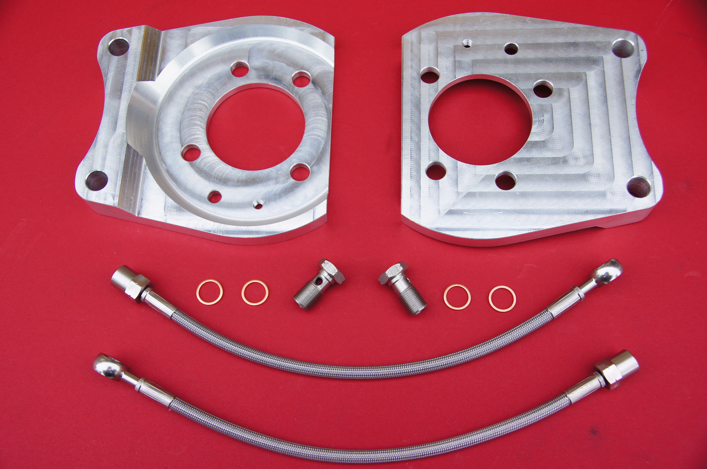
CNC Rear Mounting Brackets
292mm Vented 8 Groove Pagid Discs and Pagid Pads:

292mm Pagid Vented 8G Discs and Pads
Caliper Brackets painted:
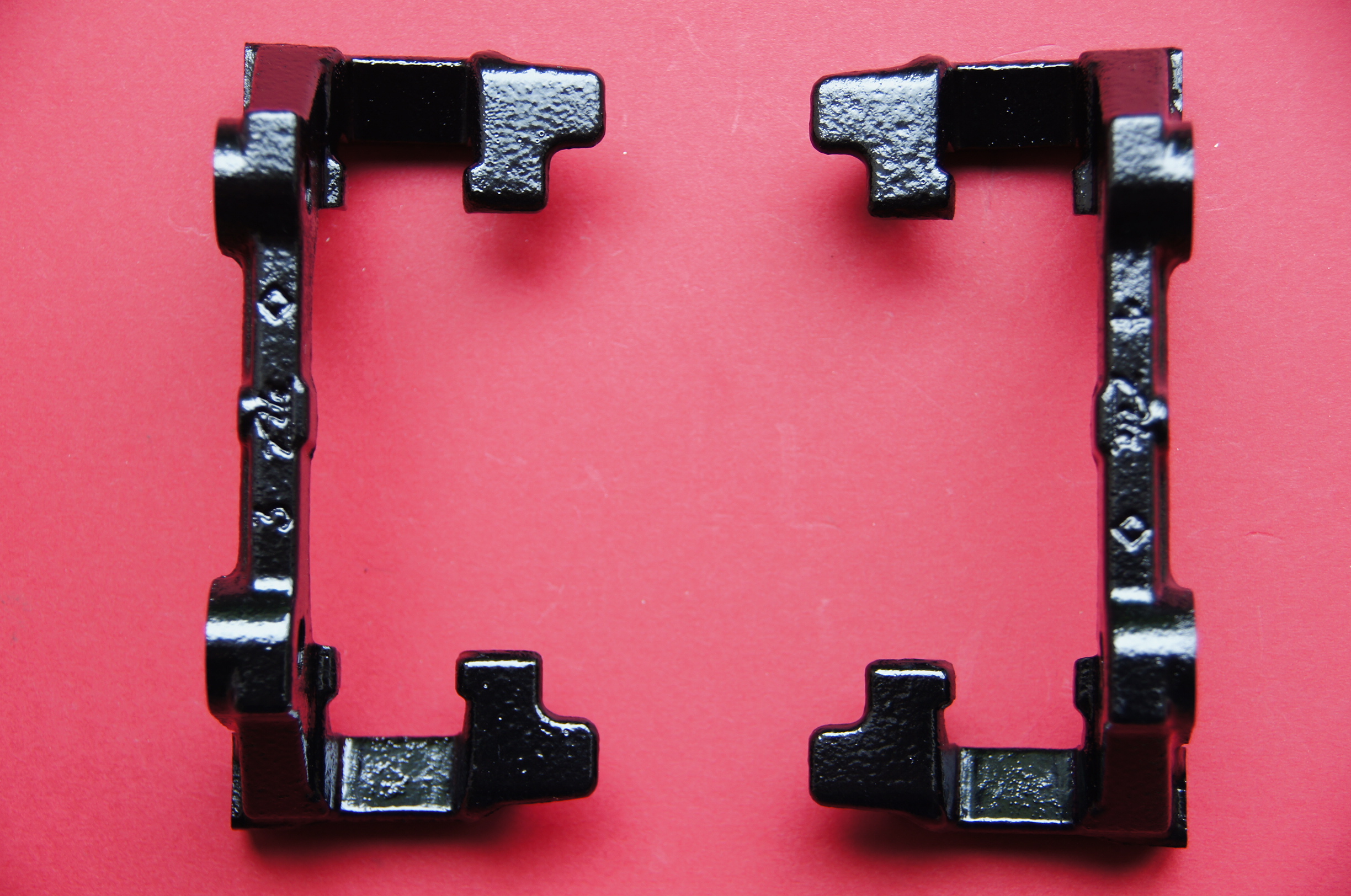
Rear Caliper Mounting Brackets
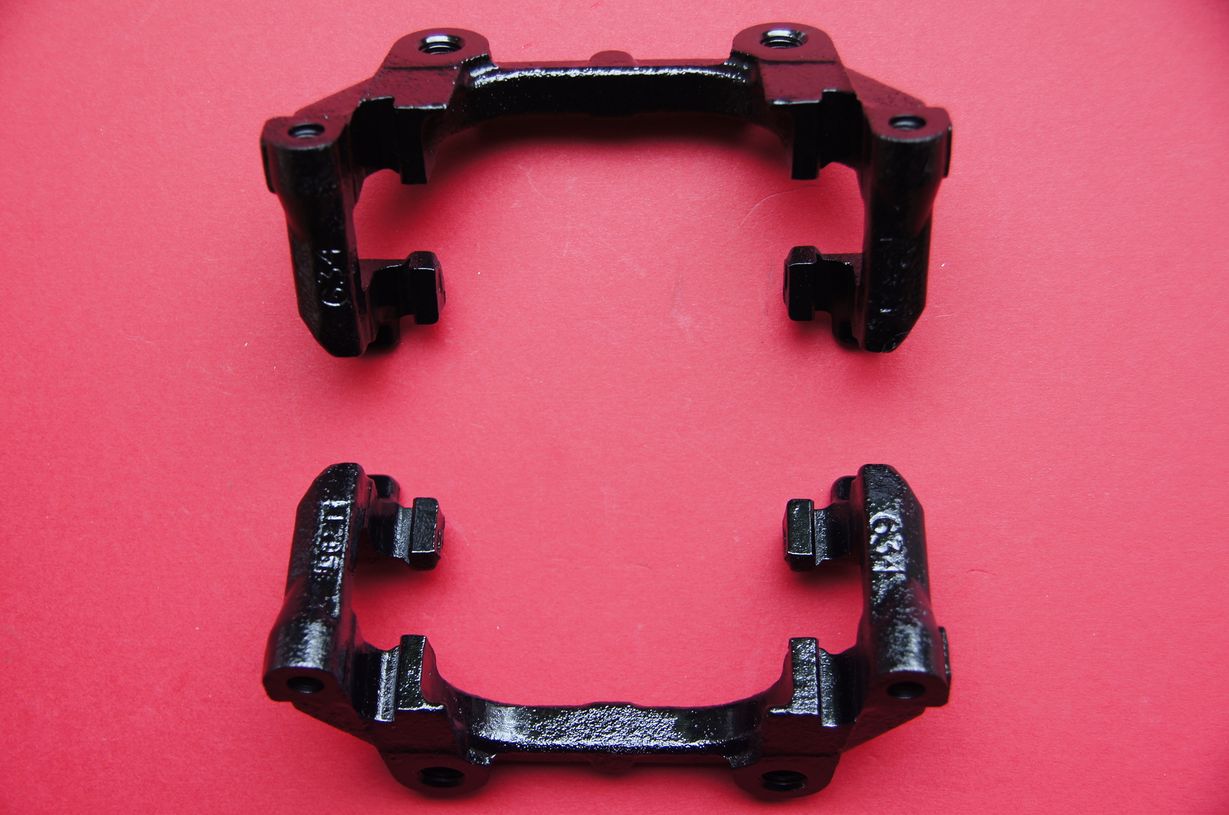
Rear Caliper Mounting Brackets

Rear Caliper Mounting Brackets
Rear Calipers painted:
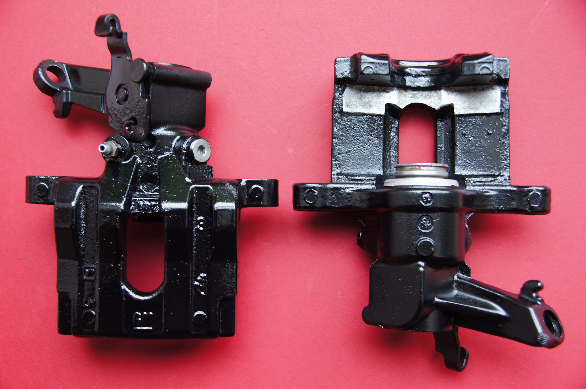
Rear Calipers
Rear Calipers
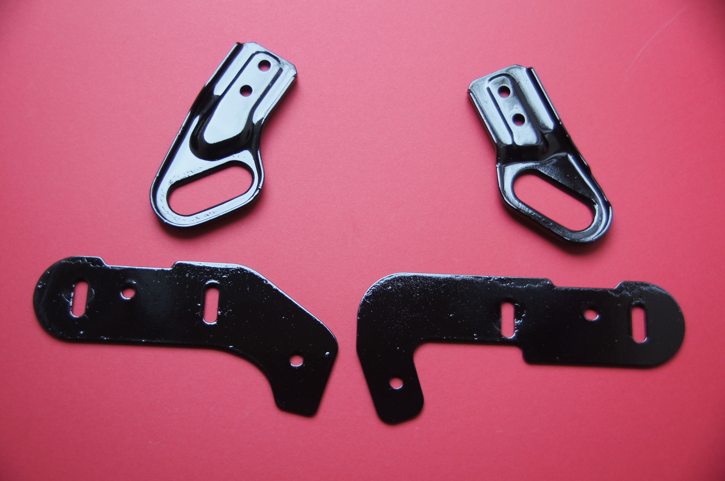
Rear Brake Backplates with the lips trimmed to fit the 292mm discs and painted:
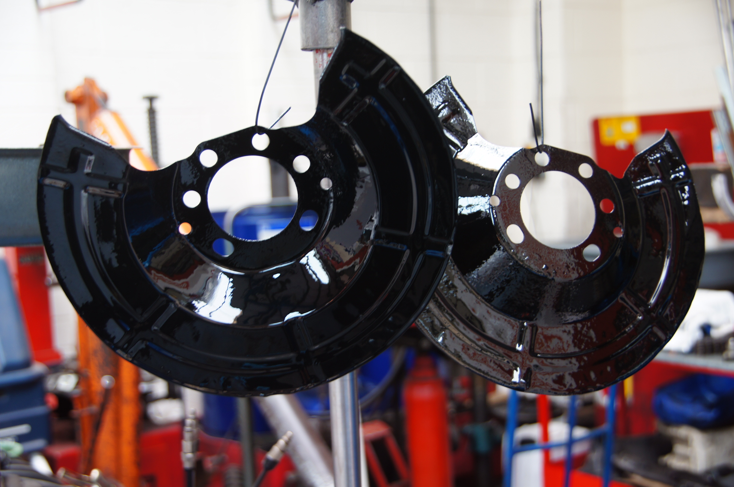
Rear Backplates
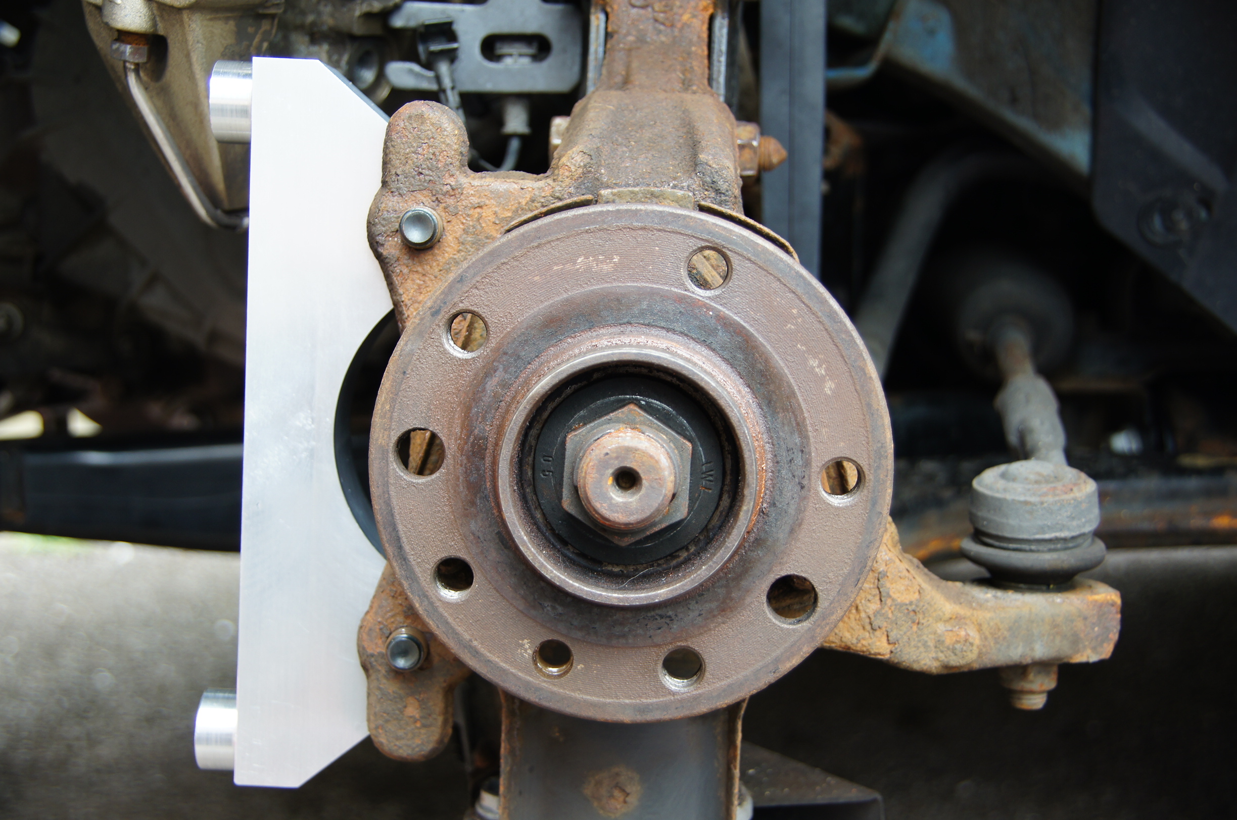
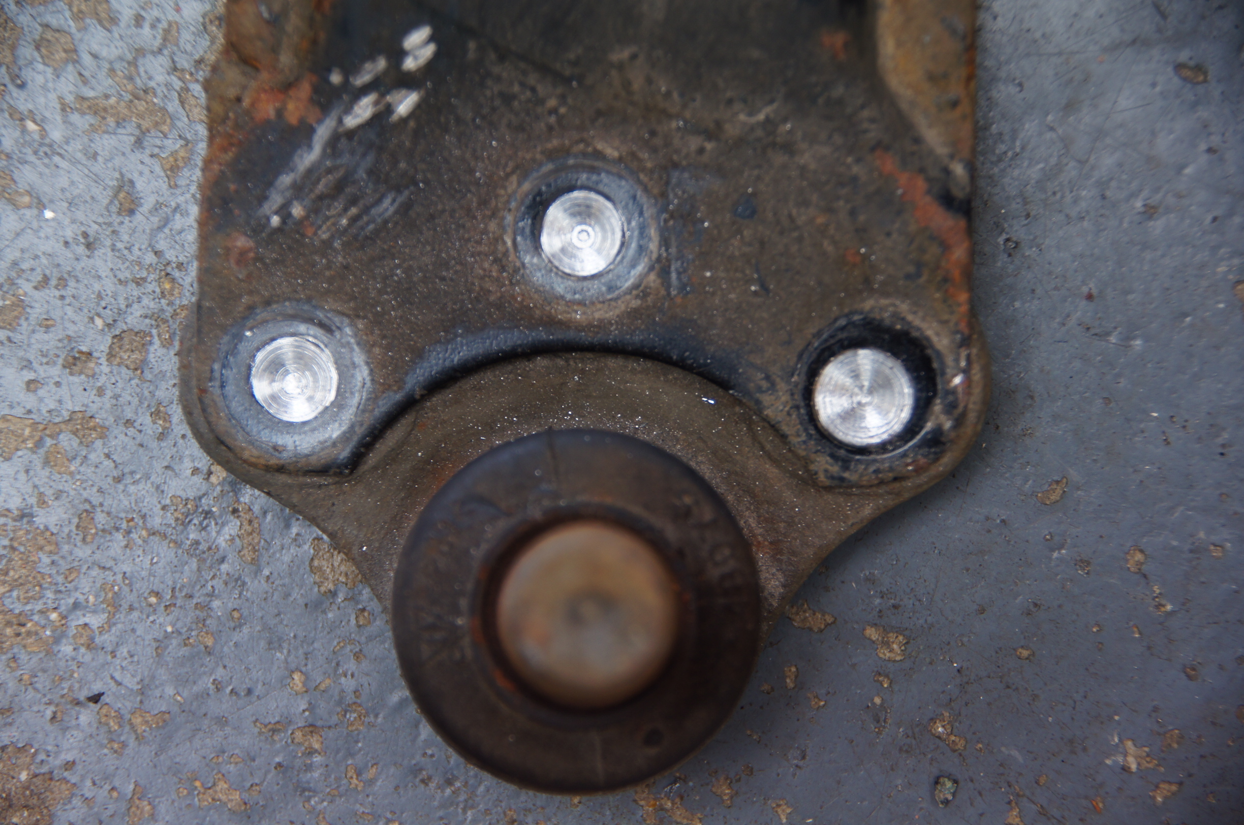
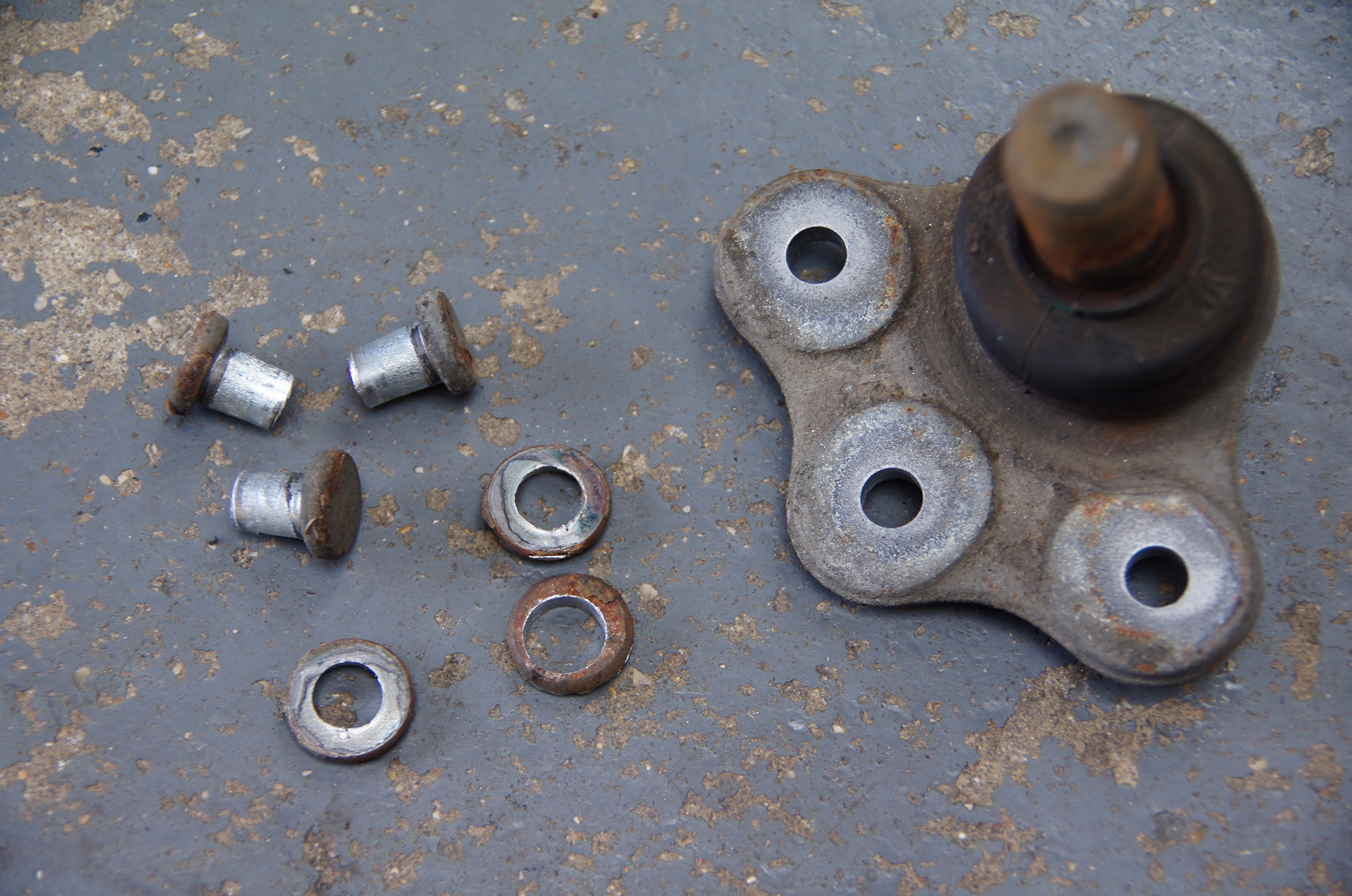
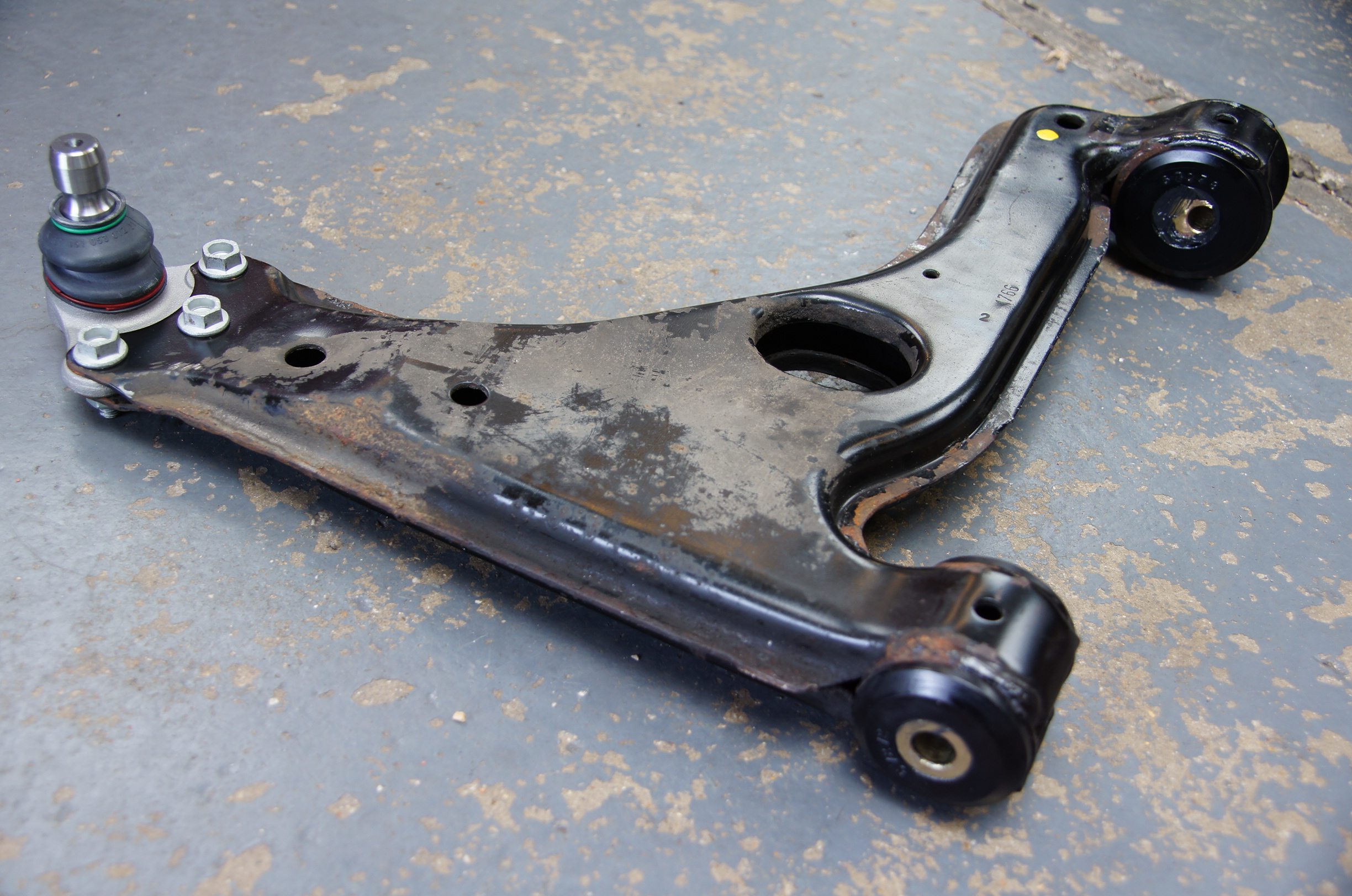
Rear Hub, original 278mm disc removed, calliper to come off next:
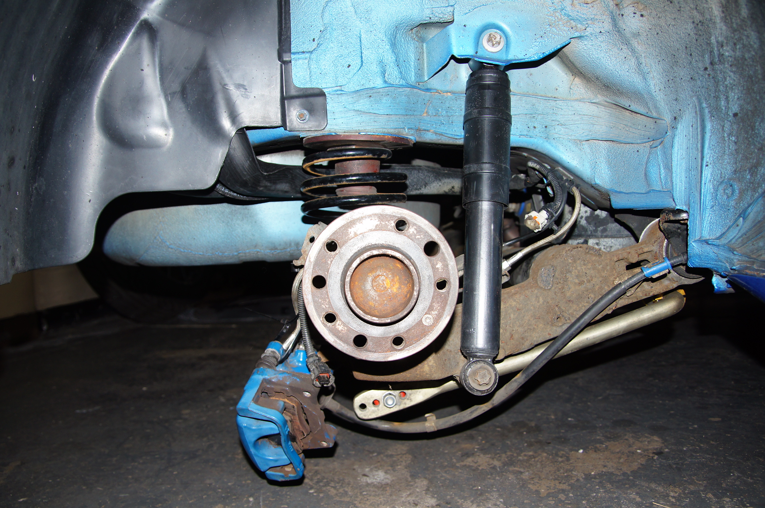
Rear Hub
The rear hub and mounting brackets are then removed. The hub has to be removed from the original mounting bracket (carefully as sometimes this can damage the ABS hub) and the hub is then fitted into the new CNC machined mounting brackets, new lock nuts are fitted and then torqued up. Finally the discs, calipers and pads are fitted and the new brake lines, then the system is bled through.
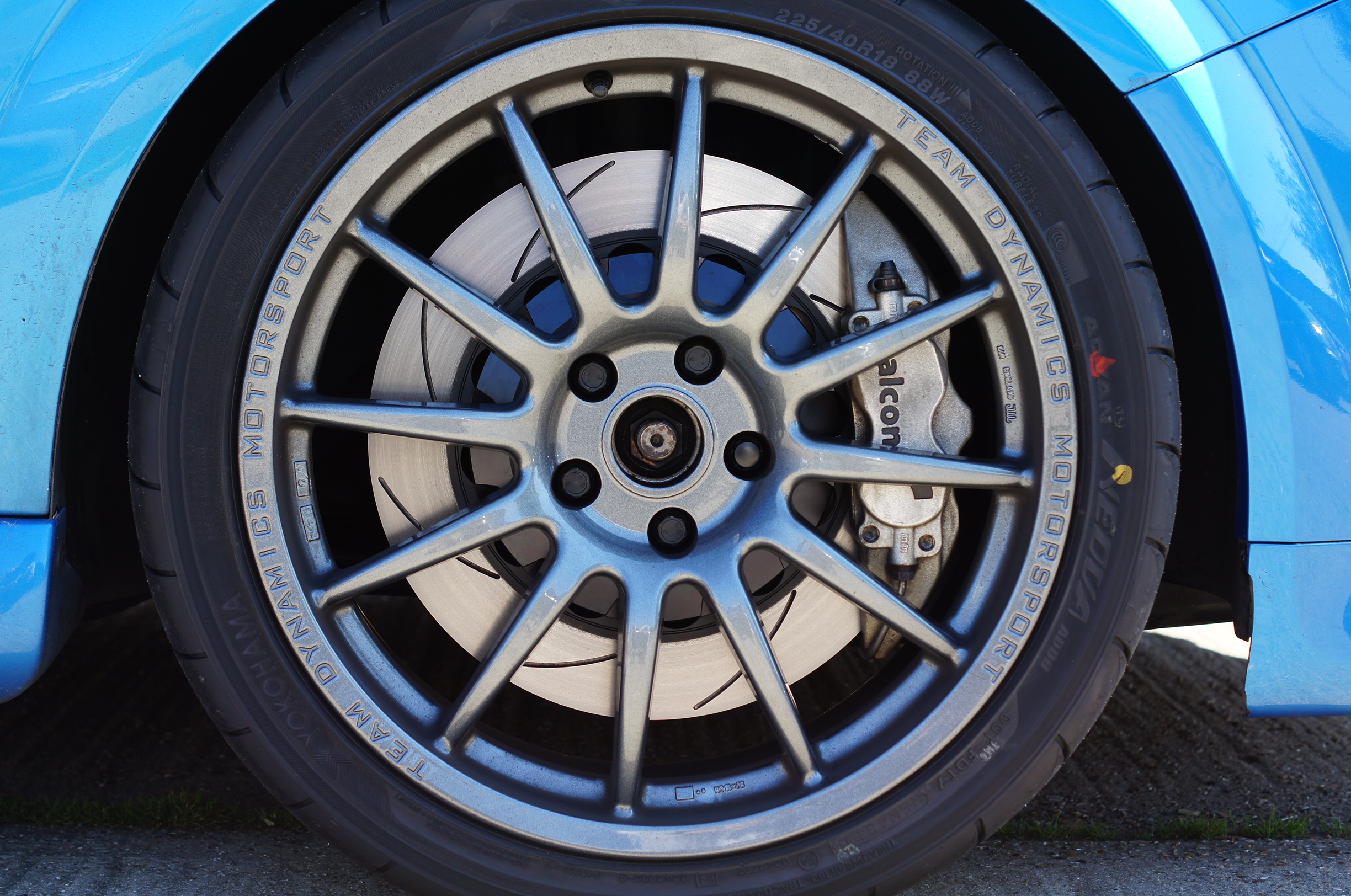
292mm Rear Brake Upgrade Fitted:
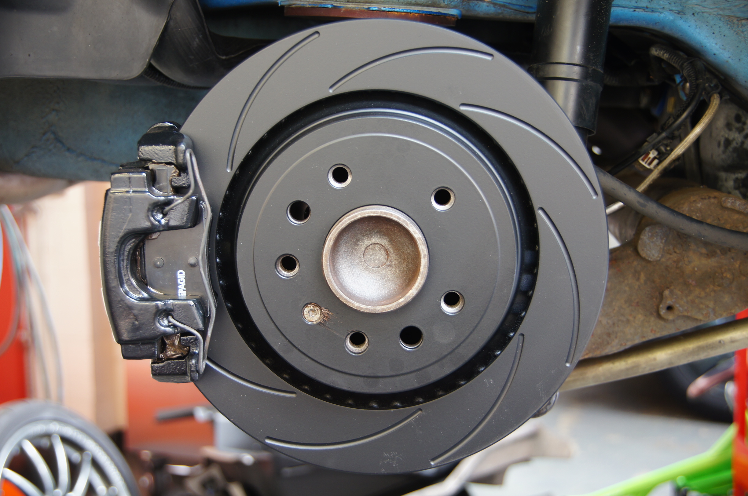
292mm Rear Brake Set Up Fitted